Band-splitting time compensation signal processing device

a signal processing and splitter technology, applied in the direction of electrical transducers, transducer details, amplifiers, etc., can solve the problems of increasing the cost, requiring a larger space, and the inability to adjust the time axis alone without changing the other characteristics, so as to suppress the occurrence of peak, improve the linearity of transfer characteristics, and reduce the effect of peak occurren

Active Publication Date: 2010-10-14
MITSUBISHI ELECTRIC CORP
View PDF8 Cites 37 Cited by
  • Summary
  • Abstract
  • Description
  • Claims
  • Application Information

AI Technical Summary

Benefits of technology

[0014]According to the band-splitting time compensation signal processing device in accordance with the present invention, it goes without saying that it can adjust the time axes of the individua

Problems solved by technology

In this case, since the same number of amplifiers as the speaker units is necessary, problems arise of increasing the cost, complicating wiring and requiring a larger space.
According to this method, however, the frequency characteristics and phase characteristics other than the time axis are corrected simultaneously, which means that it is impossible to adjust the time axis alone without changing the other

Method used


Image

  • Band-splitting time compensation signal processing device
  • Band-splitting time compensation signal processing device
  • Band-splitting time compensation signal processing device

Examples


embodiment 1

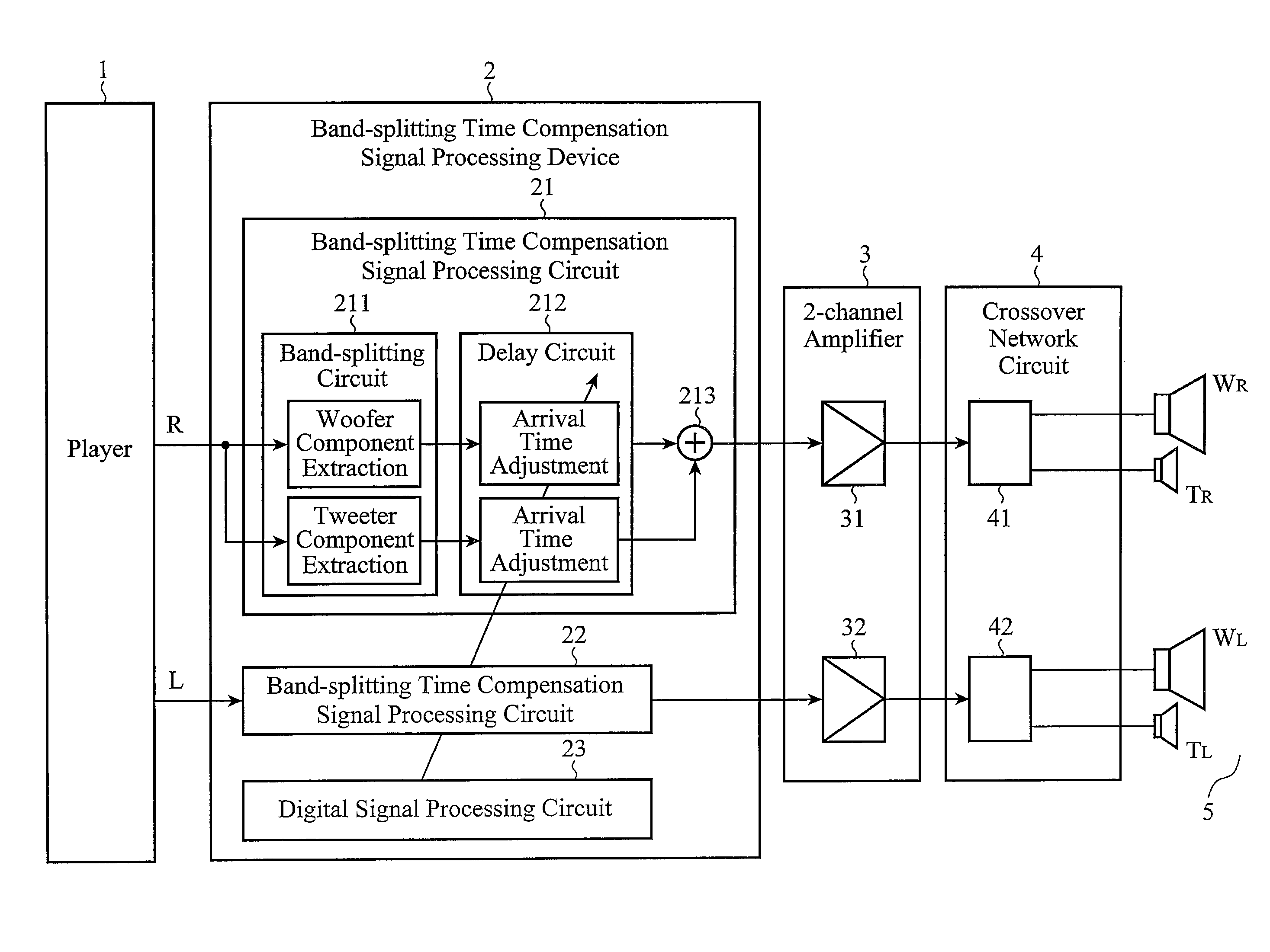
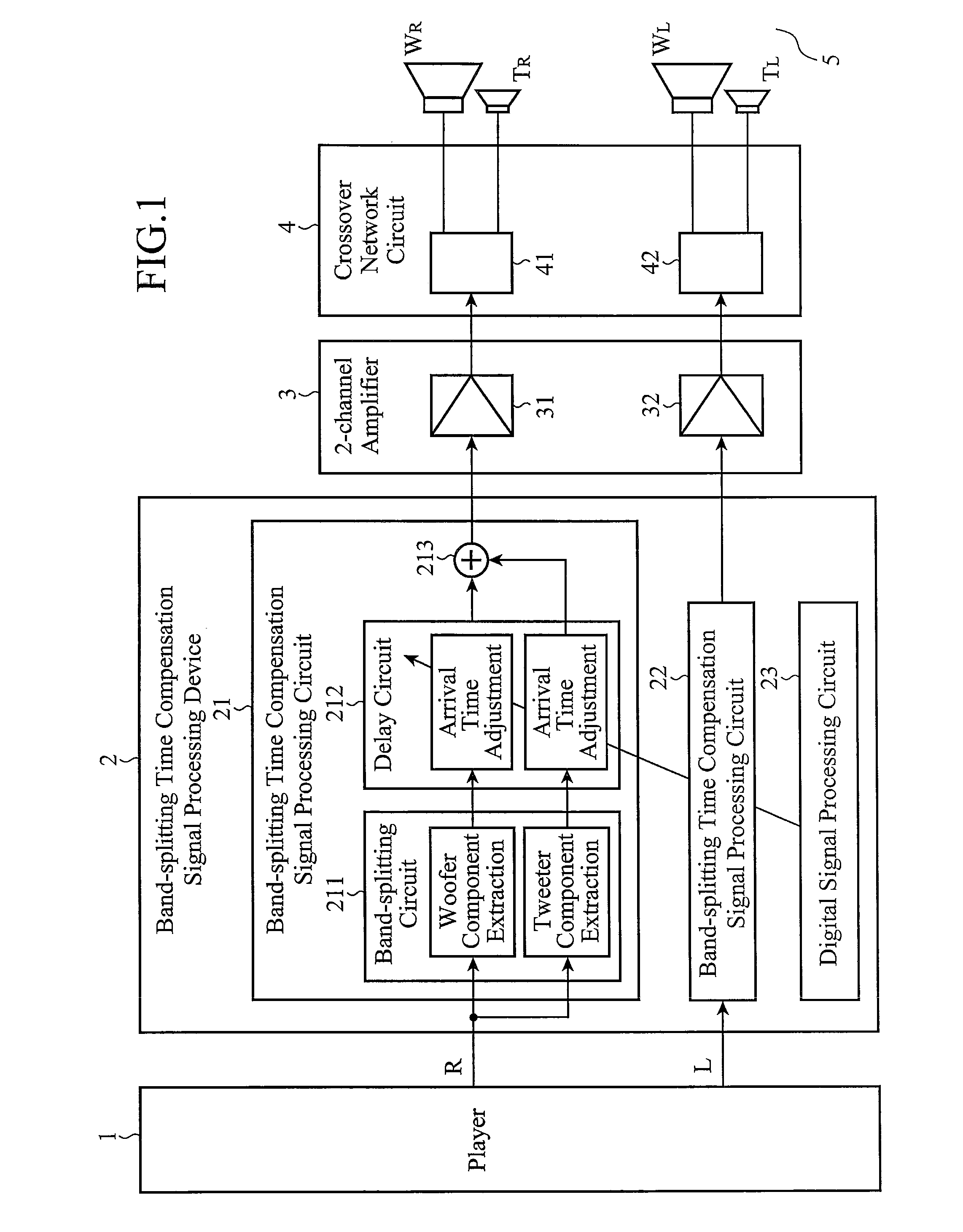
[0023]FIG. 1 is a block diagram showing an internal configuration of an audio system including a band-splitting time compensation signal processing device of an embodiment 1 in accordance with the present invention.

[0024]Here, an audio system with two channels of R and L is shown as an example. The audio system includes a player 1 serving as an input source, a band-splitting time compensation signal processing device 2, a two-channel amplifier 3, a crossover network circuit 4, and two-way speaker units 5 with woofers and tweeters.

[0025]The band-splitting time compensation signal processing device 2, which has a function of correcting the bias of the sound field resulting from the distance differences between the speaker units 5 and the listening position of a listener by adjusting the arrival time of sounds, includes an R-channel band-splitting time compensation signal processing circuit 21, an L-channel band-splitting time compensation signal processing circuit 22, and a digital si...

embodiment 2

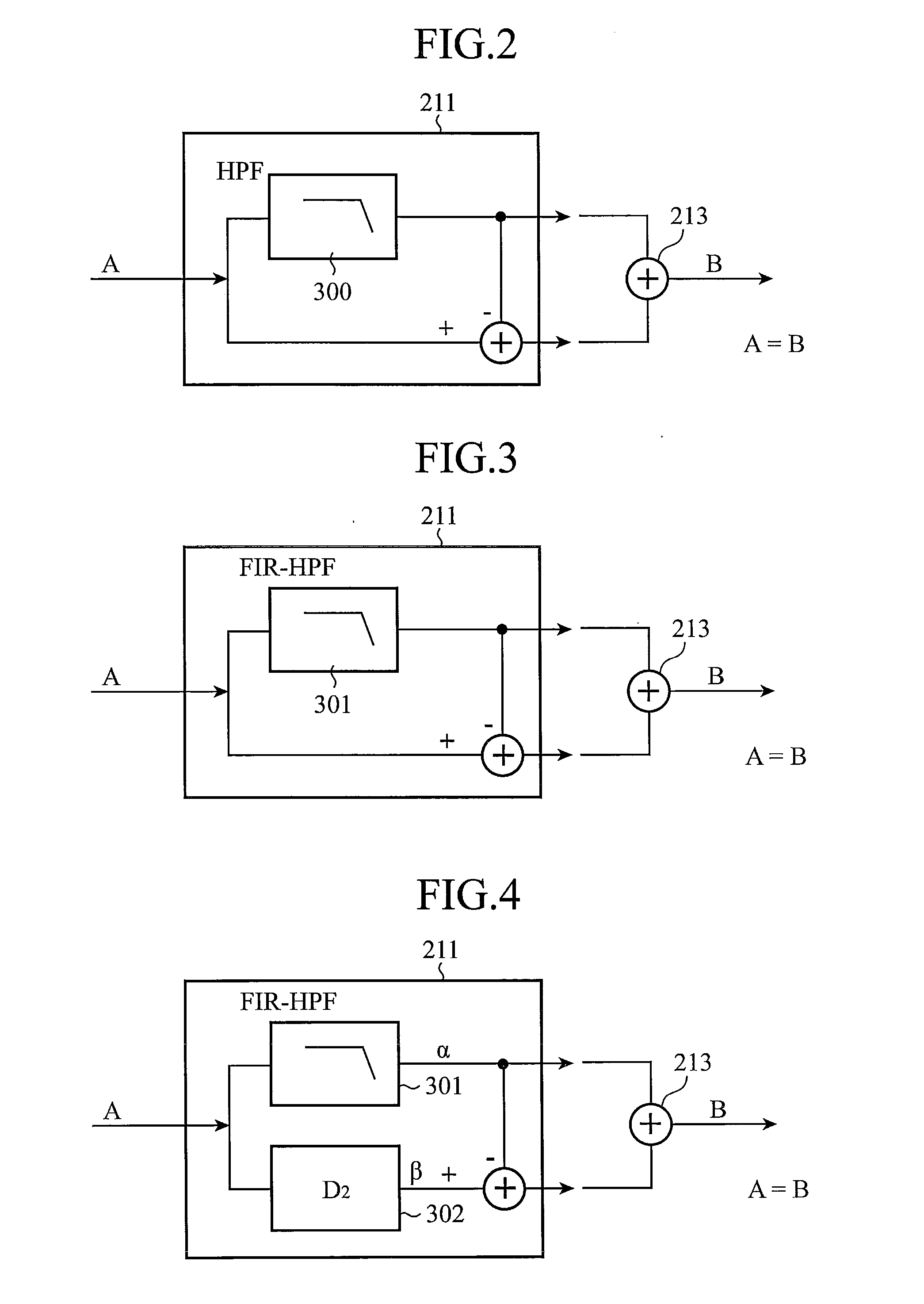
[0038]According to the band-splitting time compensation signal processing device 2 of the foregoing embodiment 1, although it can improve the linearity of the transfer characteristic at the listening position of the listener, it cannot always achieve flat frequency characteristics in the woofer component or tweeter component signal split by the difference, depending on the characteristics of the subtraction-type digital filter (subtraction-type high-pass filter 300) used for the band-splitting circuit 211 constituting the band-splitting time compensation signal processing circuit 21.

[0039]For this reason, as an example of its circuit configuration is shown in FIG. 3, the embodiment 2 which will be described below employs an FIR linear phase high-pass filter 301 consisting of an FIR digital filter as the band-splitting circuit 211 constituting the band-splitting time compensation signal processing circuit 21. Incidentally, as for the audio system to which the embodiment 2 is applied,...

embodiment 3

[0044]According to the foregoing embodiment 2, although the FIR filter with the linear phase characteristics reflects its feature in the tweeter component signal extracted by the FIR linear phase high-pass filter 301, it does not reflect its feature in the woofer component signal split by subtracting the tweeter component signal.

[0045]For this reason, as an example of its circuit configuration is shown in FIG. 4, the embodiment 3 which will be described below inserts a delay circuit 302 (second delay circuit) having a delay D2 corresponding to the group delay time of the FIR linear phase high-pass filter 301 into a path β for extracting the woofer component signal split by subtracting the tweeter component signal from the R-channel input signal in the band-splitting time compensation signal processing circuit 21.

[0046]The same is true for the L-channel input signal. Here, the term “group delay” refers to a phenomenon that outputs a toneburst with a little delay, and the term “group ...


PUM


Abstract

A band-splitting time compensation signal processing device 2 includes a band-splitting circuit 211 for extracting, after extracting a signal of a high-frequency band component or low-frequency band component from an input signal, a signal of the low-frequency band component or high-frequency band component by subtracting the signal of the high-frequency band component or low-frequency band component from the input signal; a delay circuit 212 for delaying, for adjusting arrival time, at least one of the high-frequency band component and low-frequency band component output from the band-splitting circuit 211; and a mixing circuit 213 for combining the high-frequency band component or low-frequency band component output from the delay circuit 212 with the low-frequency band component or high-frequency band component output from the band-splitting circuit 211.

Description

TECHNICAL FIELD[0001]The present invention relates to a band-splitting time compensation signal processing device suitably applied to an audio system for driving a plurality of speaker units, which have reproduction bands split, with a single amplifier via a crossover network circuit.BACKGROUND ART[0002]As shown in FIG. 6, for example, as for an onboard audio system, since the distances DW R, DT R, DW L, and DT L (all of which are represented by solid lines in FIG. 6) from the two-way speaker units (right woofer WR, right tweeter TR, left woofer WL and left tweeter TL) placed in a vehicle to a listener differ, an acoustic image (represented by broken lines in FIG. 6) is pulled to the position of the closest speaker unit owing to Haas effect (precedence effect), and hence a good sound field cannot be obtained.[0003]In this case, time alignment processing (time adjustment) is carried out so that sounds emitted from the four speaker units arrive at the listener position simultaneously ...

Claims


Application Information

Patent Timeline
IPC IPC(8): H03F99/00
CPCH04R2499/13H04R3/14H04S3/002
Inventor TERAMOTO, KOHEIKIMURA, MASARUNAKADA, TSUYOSHI
Owner MITSUBISHI ELECTRIC CORP
Why Eureka
Try Eureka