Toner, toner production method, and image forming device using the same

a technology of toner and production method, applied in the field of toner, toner production method, and image forming device using the same, can solve the problems of long time for standing still, difficult control of toner by electric field, and large particle size of toner, and achieve the effect of suppressing the scattering of toner and excellent quality images

Inactive Publication Date: 2010-10-14
SEIKO EPSON CORP
View PDF3 Cites 1 Cited by
  • Summary
  • Abstract
  • Description
  • Claims
  • Application Information

AI Technical Summary

Benefits of technology

[0031]Thus, an image forming device capable of forming excellent quality images whi

Problems solved by technology

However, a small-diameter particle toner is likely to scatter, which causes problems of scattering of the toner into image forming devices and occurrence of toner stain, and further it has become an object to prevent the toner from scattering into the air from the devices.
A reduction in the toner particle size increases the ratio of the van der Waals force relative to the ratio of the static electricity force, and thus it has become difficult to control the toner by the electric field.
Therefore, when the toner that cannot be controlled by the electric field scatters during development or the like, the toner is likely to scatter in the air outside devices while being carried by the air current from a cooling f

Method used


Image

  • Toner, toner production method, and image forming device using the same
  • Toner, toner production method, and image forming device using the same
  • Toner, toner production method, and image forming device using the same

Examples


example 1

Production of Toner

Synthesis of Crosslinked Polyester Resin for Binder Resin

[0196]Raw materials, such as acids, alcohol components, and catalysts in the following composition, were charged in a 50 L reaction pot, and reacted at 240° C. under a normal pressure and a nitrogen air current for 12 hours. Thereafter, the pressure was gradually reduced, and the reaction was continued at 1.33×10³ Pa. The reaction was pursued by the softening point based on ASTM E28-517. When the softening point reached 160° C., the reaction was terminated.

Terephthalic acid3.9parts by massIsophthalic acid9.06parts by massEthylene glycol2.54parts by massNeopentylglycol4.26parts by massTetrabutyl titanate0.1part by massEpiclon 8300.3part by mass(Bisphenol F type epoxy resin, manufacturedby Dainippon Ink and Chemicals Ltd., Epoxyequivalent of 170 (g / eq))Cardula E0.1part by mass(Alkyl glycidyl ester, manufactured byShell Japan), Epoxy equivalent of 250 (g / eq)

[0197]The obtained polymer was a colorless solid and h...

example 2

[0219]In the unification process, when the unification proceeded to reach 4 μm, the stirring rate was increased to 120 min−1, the stirring was continued for 30 minutes, 0.1 m3 of water was added dropwise, and then the unification was stopped.

[0220]Thereafter, classification and drying were performed in the same manner as in Example 1, and thereafter an evaluation test was performed in the same manner as in Example 1. The results are shown in Table 1.

example 3

[0221]A toner was prepared in the same manner as in Example 2, except that, after classifying and drying, 0.2% by mass of silicone oil (KF-96-200CS manufactured by Shin-Etsu Chemical Co., Ltd., 100% dimethyl polysiloxane) having a kinetic viscosity at 25° C. of 200 mm2 / s was added and an evaluation test was performed in the same manner as in Example 1. The results are shown in Table 1.


PUM

PropertyMeasurementUnit
Percent by massaaaaaaaaaa
Diameteraaaaaaaaaa

Abstract

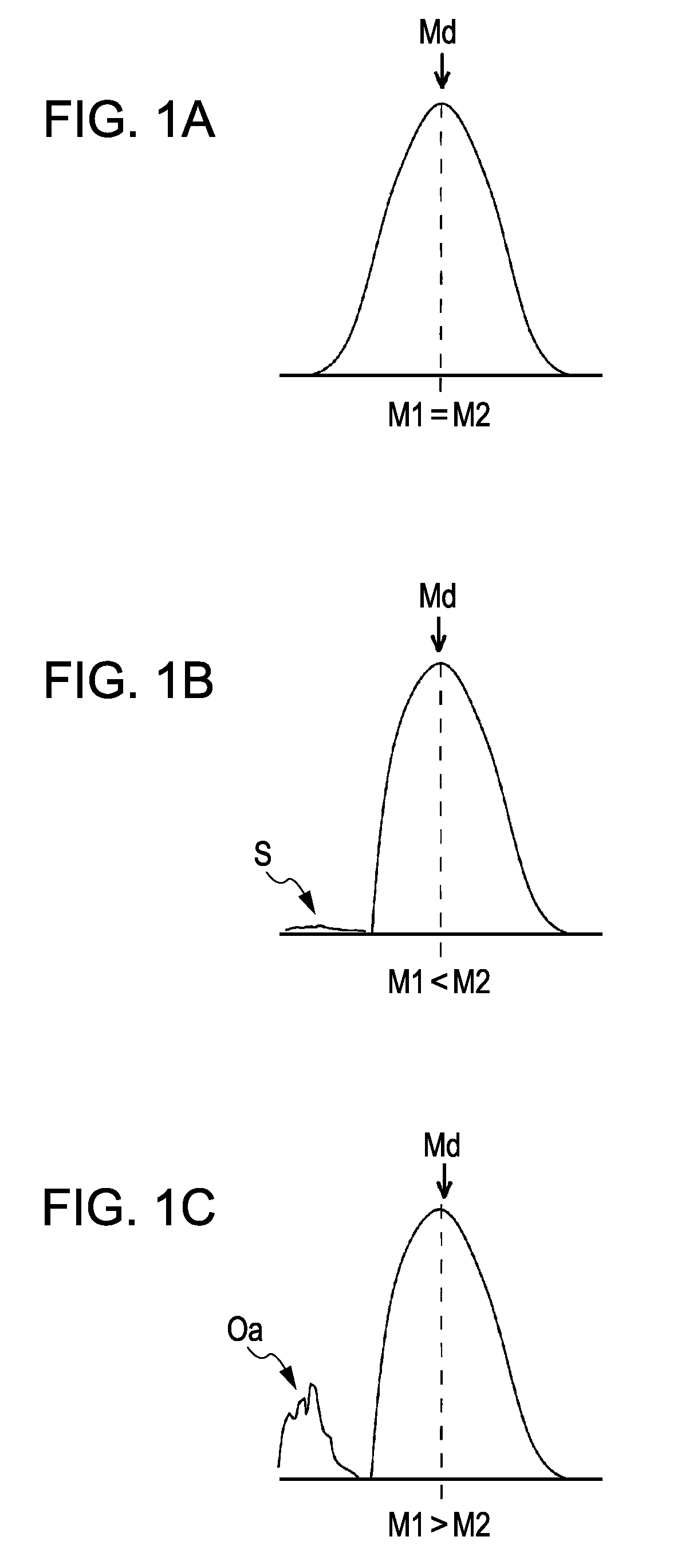
A toner, has a number mode diameter of 3 μm or more and 6 μm or lower and a particle size distribution of a toner including an externally-applied agent in the range of 0.6 μm to 400 μm in which the number frequency of a toner smaller than the number mode diameter is smaller than the number frequency of a toner equal to or larger than the number mode diameter.

Description

CROSS-REFERENCE TO A RELATED APPLICATION[0001]The entire disclosure of Japanese Patent Application No. 2009-096811, filed Apr. 13, 2009 is expressly incorporated by reference herein.BACKGROUND[0002]1. Technical Field[0003]The present invention relates to an electrostatic latent image developing toner for developing electrostatic latent images on a latent image support in image output devices, such as copying machines, printers, or faxes, a toner production method, and an image forming device using the same.[0004]2. Related Art[0005]In image output devices, such as electrophotographic copying machines, printers, and faxes, the diameter of toner particles for use in image formation has been increasingly reduced in order to meet demands of increasing the resolution of printed image, increasing the gradation thereof, reducing the amount of waste toners, reducing the consumption energy by lowering fixing temperatures, etc.[0006]However, a small-diameter particle toner is likely to scatte...

Claims


Application Information

Patent Timeline
IPC IPC(8): G03G9/00G03G15/08
CPCG03G9/0804G03G9/0817G03G9/0819G03G9/0821G03G2215/0614G03G9/08795G03G9/08797G03G9/09708G03G9/08755
Inventor YAMAZAKI, SOICHIFUKUMOTO, TAKATOMOOKADA, HIDEKIONO, TOSHIKAZU
Owner SEIKO EPSON CORP
Why Eureka
Try Eureka