

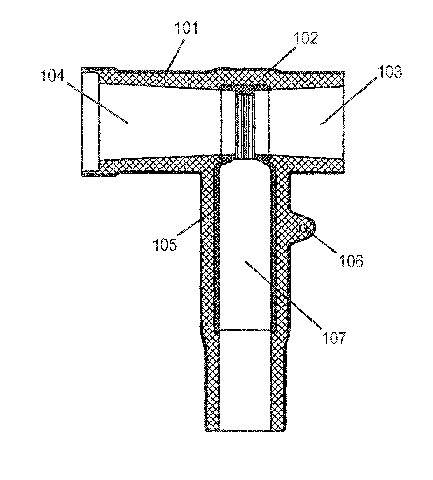
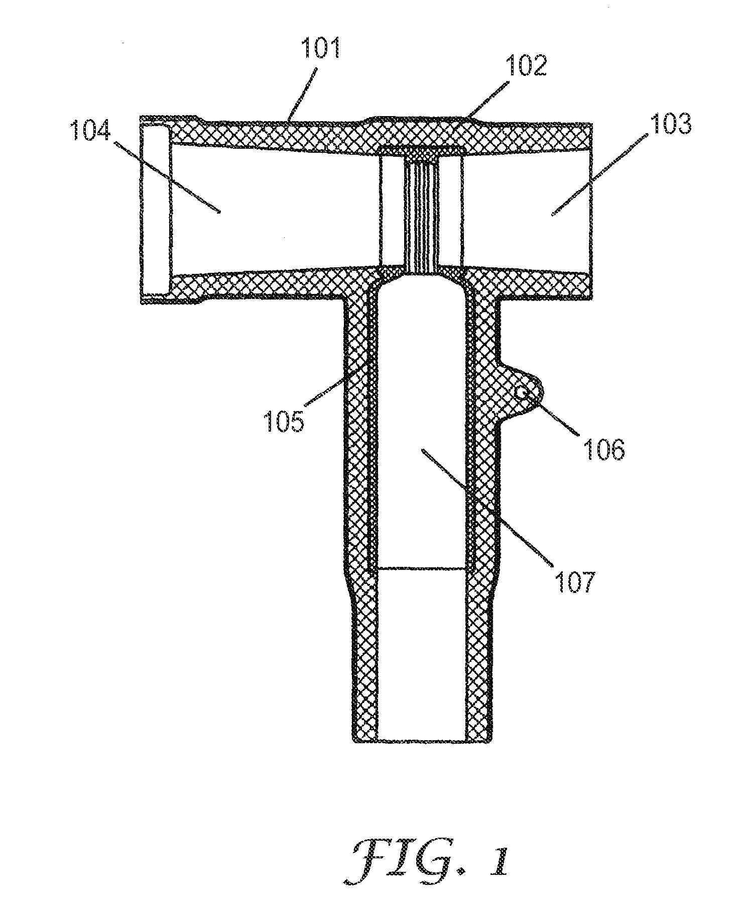
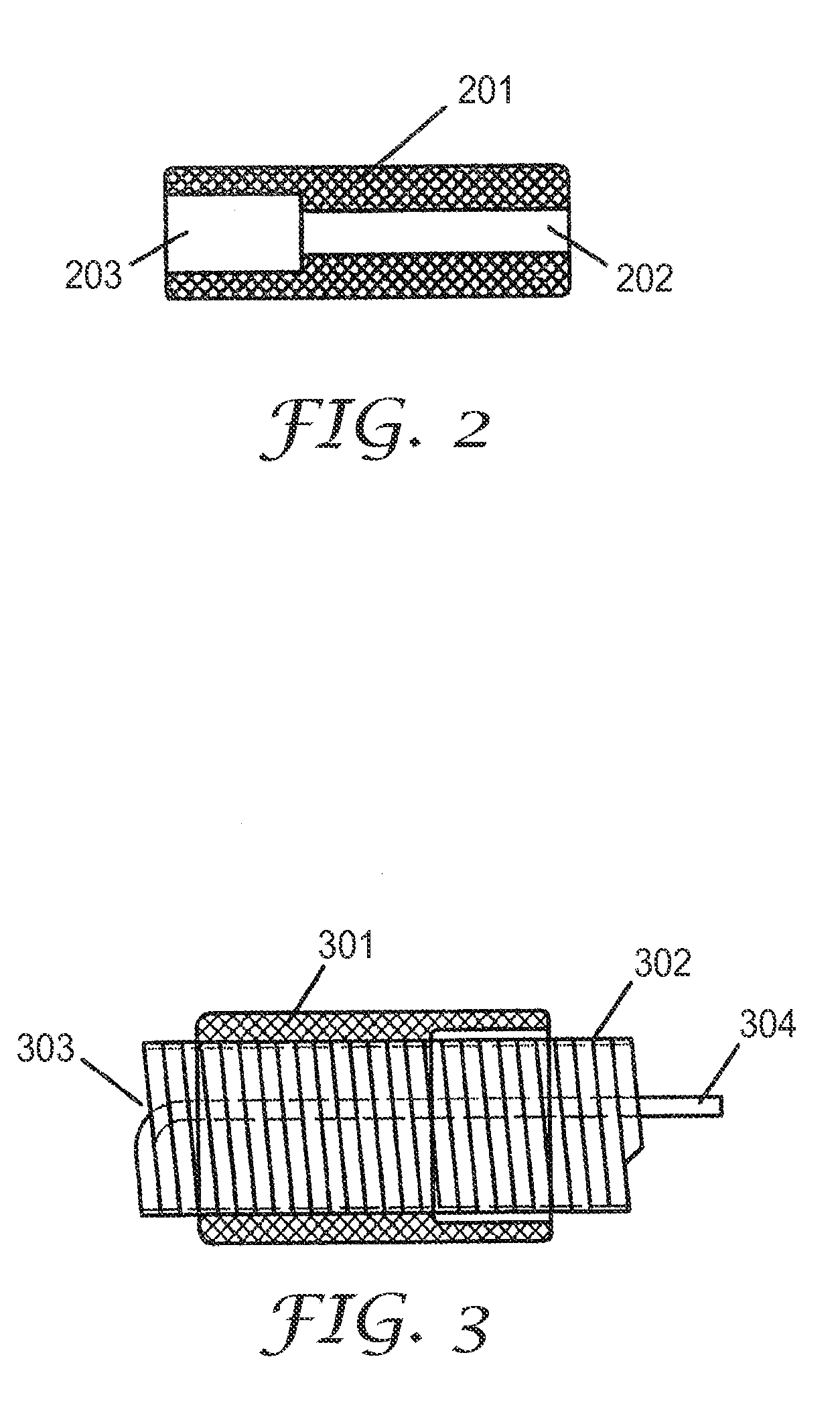
Adapter, a cable connector with the adapter and a cable connector assembly
a technology of adapter and cable connector, which is applied in the direction of coupling device connection, coupling protective earth/shielding arrangement, and securing/insulating coupling contact member, etc., can solve the problem of difficult mounting of the adapter, the prior adapter cannot be easily interchanged, and the manufacturing process of the adapter is complicated. , to achieve the effect of a wider range of cross sections and simplified manufacturing process
- Summary
- Abstract
- Description
- Claims
- Application Information
AI Technical Summary
Benefits of technology
Problems solved by technology
Method used
Image

Examples
example 1
[0049]Using silicon rubber with dielectric constant value 30 to manufacture the above-mentioned adapter with a single layer structure, wherein the thickness of the adapter is 9 mm, and using the silicon rubber, the insulating strength of which is more than 22 kV / mm, to manufacture the T-shaped connector. Then, testing the performances of the adapter by mounting the adapter to a cable with a cross section area 185 mm2, made of cross-linked polyethylene with the voltage class 26 / 35 kV. The test result is as follows.
TABLE 1Test on the power frequency withstand voltage and the partialdischarge (background AC withstand voltage (50 Hz) 117 kV45 kVSample 130 minutes, no breakdownSample 230 minutes, no breakdownSample 330 minutes, no breakdown
example 2
[0050]Using silicon rubber with dielectric constant value 15 to manufacture the above-mentioned adapter with a single layer structure, wherein the thickness of the adapter is 9 mm, and using the silicon rubber, the insulating strength of which is more than 22 kV / mm, to manufacture the T-shaped connector. Then, testing the performances of the adapter by mounting the adapter to a cable with a cross section area 185 mm2, made of cross-linked polyethylene with the voltage class 12 / 20 kV. The test result is as follows.
TABLE 2Test on the power frequency withstand voltage and the partialdischarge (background AC withstand voltage (50 Hz) 54 kV21 kVSample 430 minutes, no breakdownSample 530 minutes, no breakdownSample 630 minutes, no breakdown
example 3
[0051]Using silicon rubber with dielectric constant value 7 to manufacture the above-mentioned adapter with a single layer structure, wherein the thickness of the adapter is 9 mm, and using the silicon rubber, the insulating strength of which is more than 22 kV / mm, to manufacture the T-shaped connector. Then, testing the performances of the adapter by mounting the adapter to a cable with a cross section area 185 mm2, made of cross-linked polyethylene with the voltage class 8.7 / 15 kV. The test result is as follows.
TABLE 3Test on the power frequency withstand voltage and the partialdischarge (background AC withstand voltage (50 Hz) 39 kV15 kVSample 730 minutes, no breakdown0.75pCSample 830 minutes, no breakdown0.69pCSample 930 minutes, no breakdown0.81pC
[0052]Based on above examples, by using the elastic material with stress control function, the present invention solves the technical problem of the prior arts with the two-layer-structure in which an additional stress control layer mu...
PUM
 Abstract
Description
Claims
Application Information