Blood test apparatus and method of controlling the same

Inactive Publication Date: 2010-10-14
PANASONIC HEALTHCARE HLDG CO LTD
View PDF4 Cites 20 Cited by
  • Summary
  • Abstract
  • Description
  • Claims
  • Application Information

AI Technical Summary

Benefits of technology

[0019]According to the present invention, it is possible to collect a small amount of blood required and enough

Problems solved by technology

These preparation works are troublesome for diabetes patients with poor eyesight.

Method used


Image

  • Blood test apparatus and method of controlling the same
  • Blood test apparatus and method of controlling the same
  • Blood test apparatus and method of controlling the same

Examples


Example

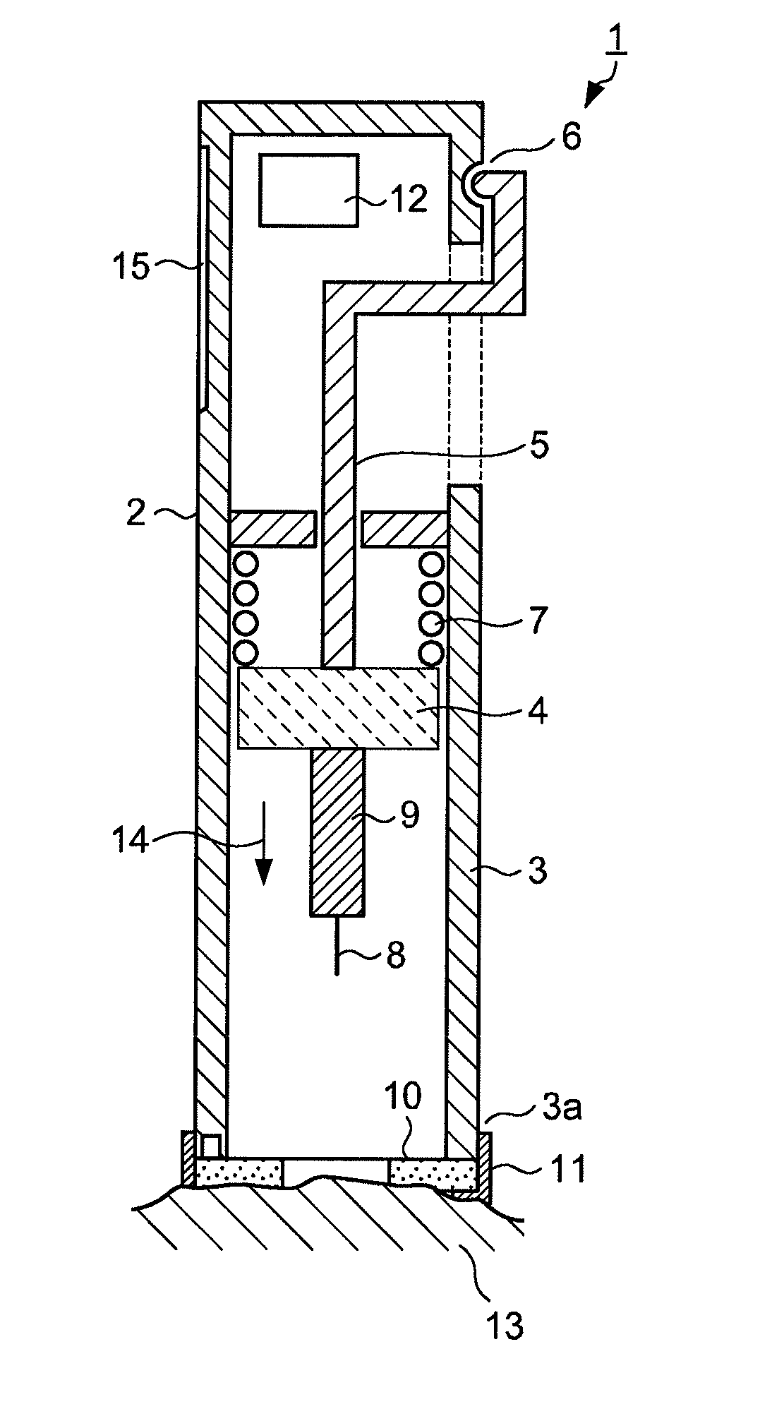
[0090]The blood test apparatus of the present invention will be described below with reference to the drawings. Common parts in the figures will be assigned the same reference numerals without further explanations.

[0091]Overall View 1 of the Apparatus

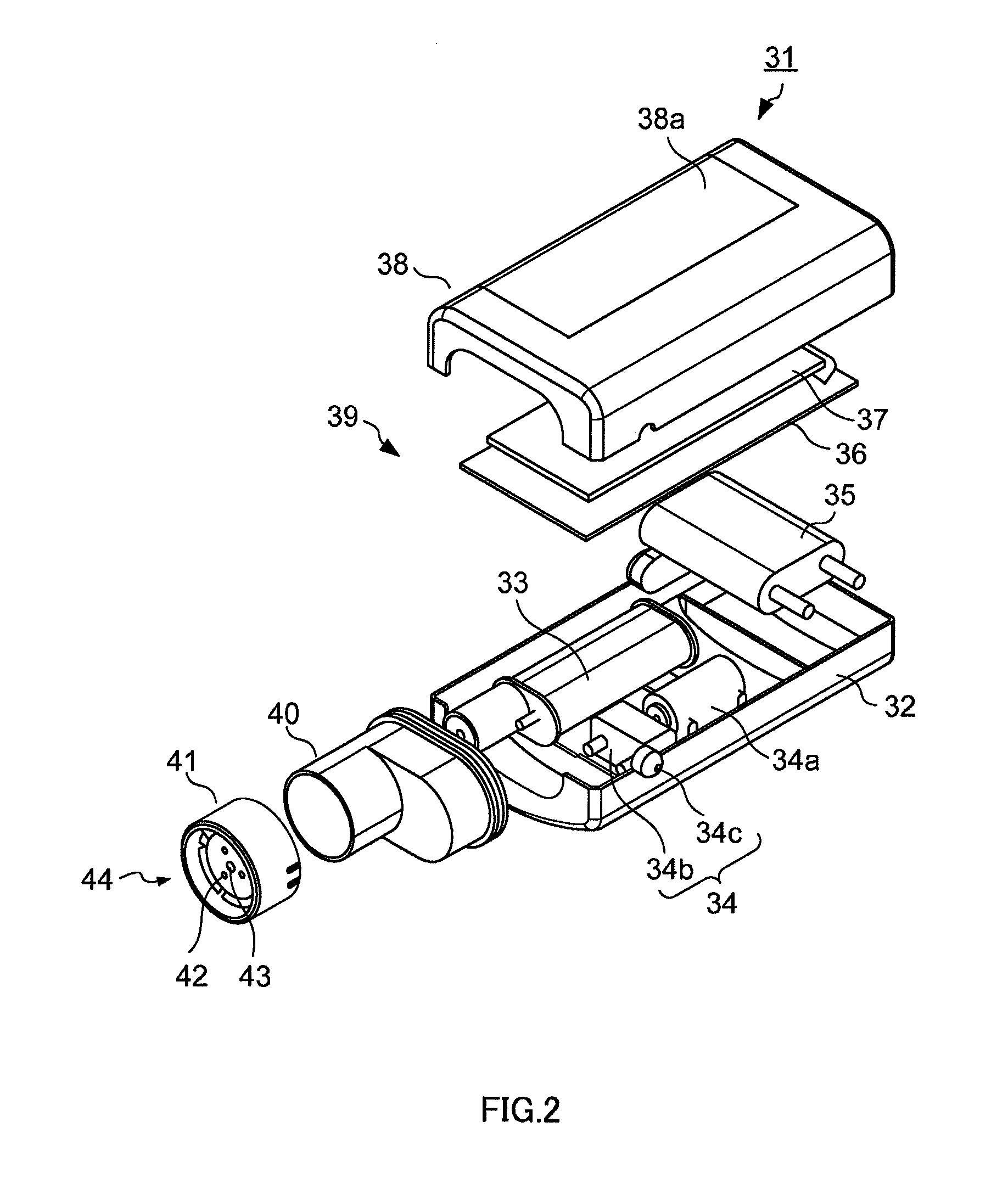
[0092]FIG. 2 is an exploded assembly perspective view showing a first example of the overall configuration of the blood test apparatus including the laser perforation apparatus of the present invention.

[0093]The interior of lower case 32 of blood test apparatus 31 shown in FIG. 2 accommodates components including: laser emitting apparatus 33; negative pressure means 34 which is configured with suction pump (negative pressure pump) 34a, pump valve unit 34b and vent switch 34c; battery 35 which supplies power to electrical components; electrical circuit section 36 which is mounted on these components; and display section 37 which is mounted on electrical circuit section 36, and, for example, made of liquid crystal.

[0094]Apparatus body 39 ...


PUM


Abstract

A blood test apparatus having a simple constitution whereby stable measurement can be conducted by surely sampling the blood in an amount being small but sufficient for the test without placing too much burden on a patient.
When a first skin contact sensor of this apparatus detects the skin, driving of a negative pressure unit is initiated (time point 166a). Thus, the skin rises and comes into contact with a second skin contact sensor (time point 166b). After piercing into the skin at time point 166c, the negative pressure supply is once ceased. Next, the negative pressure is applied again at time point 166d for a definite period of time. Thus, the opening in the skin is broadened, which facilitates the flow out of the blood (16).

Description

TECHNICAL FIELD[0001]The present invention relates to a blood test apparatus and its control method used to examine blood components, for example.BACKGROUND ART[0002]Diabetes patients need to measure the blood sugar level regularly and administer insulin based on the blood sugar level to maintain a normal blood sugar level. To maintain this normal blood sugar level, diabetes patients need to measure the blood sugar level regularly, sample a small amount of blood from fingertips using a blood test apparatus, and measure the blood sugar level from this sampled blood.[0003]The conventional blood test apparatus generally uses a needle as a means for puncturing skin (see Patent Document 1, for example). As shown in FIG. 1, conventional blood test apparatus 1 which uses a needle as a puncturing means, includes: housing 2 that forms a chassis; cylindrical body 3 that is provided at which one side of housing 2 opens; plunger 4 that moves back and forth inside cylindrical body 3; handle 5, o...

Claims


Application Information

Patent Timeline
IPC IPC(8): A61B5/151
CPCA61B5/14A61B5/14535A61B5/6843A61B5/15134A61B5/157A61B5/1486A61B5/150022A61B5/150076A61B5/150099A61B5/150145A61B5/150213A61B5/150229A61B5/150259A61B5/150358A61B5/150755A61B5/150954A61B5/15138A61B5/1405A61B5/151
Inventor FUJIWARA, MASAKIAMANO, YOSHINORIHAMANAKA, KENICHIUCHIYAMA, MOTONORINADAOKA, MASATAKAAKIYAMA, TOSHIHIROMIYOSHI, KOJI
Owner PANASONIC HEALTHCARE HLDG CO LTD
Why Eureka
Try Eureka