
Apparatus and method for internal repair of conduits

a conduit and apparatus technology, applied in the direction of shaft lining, tunnel lining, underground chamber, etc., can solve the problems of pollution, water or wastewater entering the conduit system, affecting the repair effect,

Inactive Publication Date: 2010-10-21
LINK PIPE
View PDF40 Cites 22 Cited by
  • Summary
  • Abstract
  • Description
  • Claims
  • Application Information

AI Technical Summary

Benefits of technology

[0016]The invention improves upon known internal conduit repair methods and apparatuses. More specifically, the invention provides methods and apparatuses for internally repairing conduits with a sleeve that is self-locking according to known techniques, but which prevents the unlocking or a gap creation between the repair apparatus and host pipe.
[0017]Further, the invention provides methods and apparatuses that do not require significant internal pressures to be applied to the damaged conduit section and, therefore, that do not risk the possibility of additional damage to the damaged and / or weakened conduit section.
[0018]Additionally, the invention provides for the repair of damaged openings, which might be incorporated within a damaged conduit, with a seal that can prevent the groundwater infiltration into such conduit, including relatively high ex-filtration pressure.
[0023]According to another embodiment of the invention, the reinforcement band is placed between the O-rings and the resilient membrane, and the additional layer of O-rings from solid resilient material are placed between the reinforcement band and the resilient membrane in order to restrict infiltration pressure between two adjacent O-rings and, by doing so, to decrease full external load on the core.
[0025]In a further embodiment of the invention, the expandable perforated core is provided with outwardly bent circumferential edges to create a smooth transition from the conduit diameter to the sleeve diameter.

Problems solved by technology

Over a period of time, conduit systems for carrying water or wastewater become damaged, weakened, or otherwise begin to deteriorate and leak at the joints between adjacent sections.
Such deterioration is caused by the settling of the surrounding earth adjacent the conduit system, by deterioration of the joints themselves over time, and / or by the growth of roots from trees and other plants.
In wastewater systems, wastewater can begin to leak out from damaged conduits and create problems of pollution.
In addition, damaged sections can have a groundwater infiltration problem which increases the volume of water carried to the treatment facility, thereby overburdening it.
Further, deteriorated conduits for liquid conveyance systems, including sewer systems that result in leaks can soak the surrounding terrain, sometimes creating sinkholes and exacerbating drainage problems.
Further, support for buildings, bridges, for example, provided by the terrain in which a leaking conduit is located, can become weakened, thereby risking additional property damage or more serious concerns including loss of life.
However, excavation is time-intensive and, particularly in urban areas, it creates additional problems.
Furthermore, in the repair of relatively high-pressure pipes and conduits, such as natural gas lines and water lines, there is usually a need to shut down a line, relieve pressure, and take it out from service.
Additional problems could be built up by external pressure exerted by a relatively high water level difference, such as in the case of water well exploitation.
Similar problems could happen in the case of an external environment or internal fluid temperature changes.
The reason for the subsequent failure relates to the fatigue of some materials, for instance, closed-cell plastic foam exposed to pressure loses in the gas enclosed within the cells.
A similar problem appears in the case of the gap between a rigid host pipe and an installed CIPP (Cured-In-Place-Pipe) liner.
This gap varies under an operating pressure, and as a result, any known sealing means at the ends of the CIPP liner will be destroyed.

Method used


Image

  • Apparatus and method for internal repair of conduits
  • Apparatus and method for internal repair of conduits
  • Apparatus and method for internal repair of conduits

Examples


Embodiment Construction

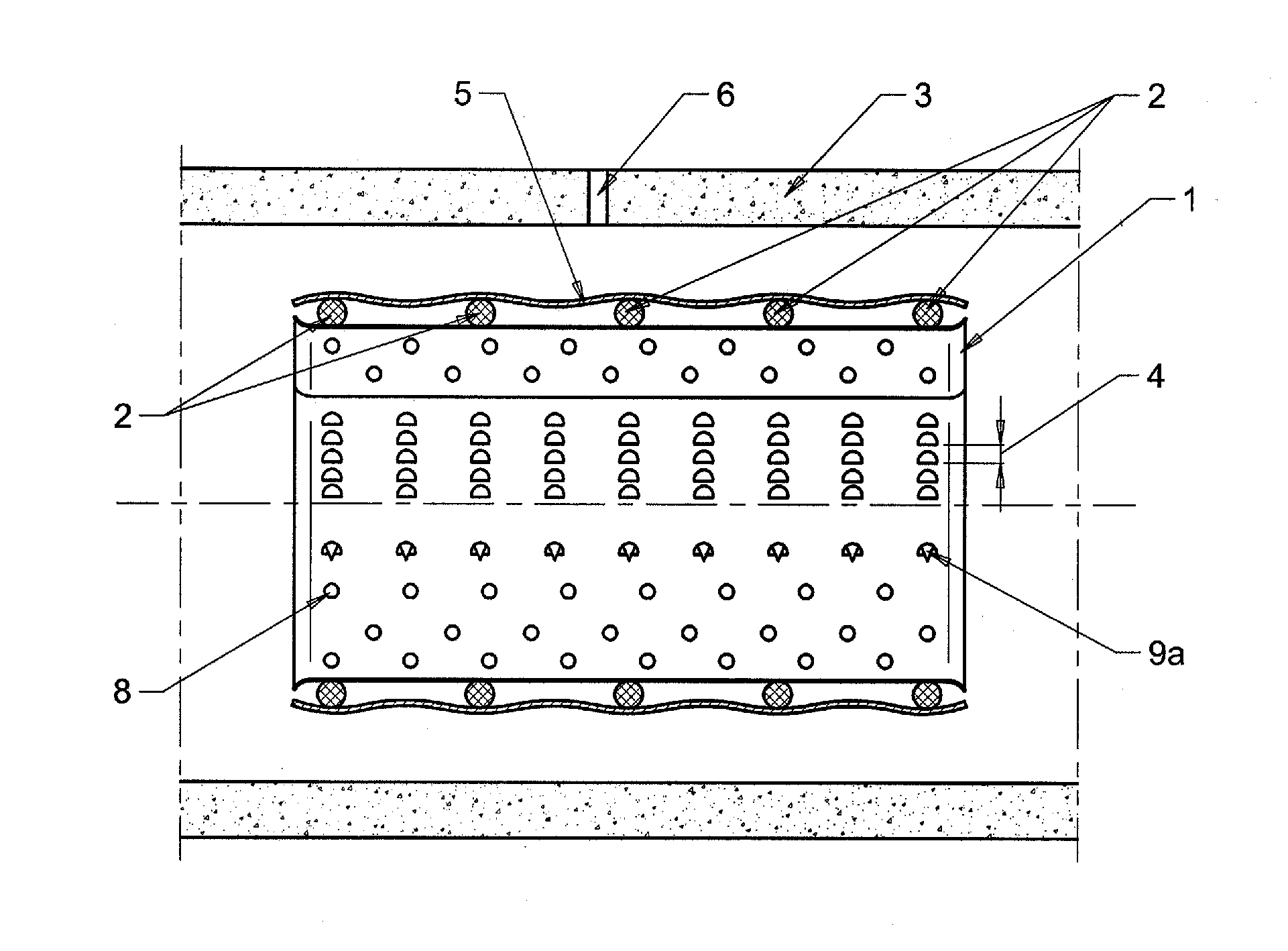
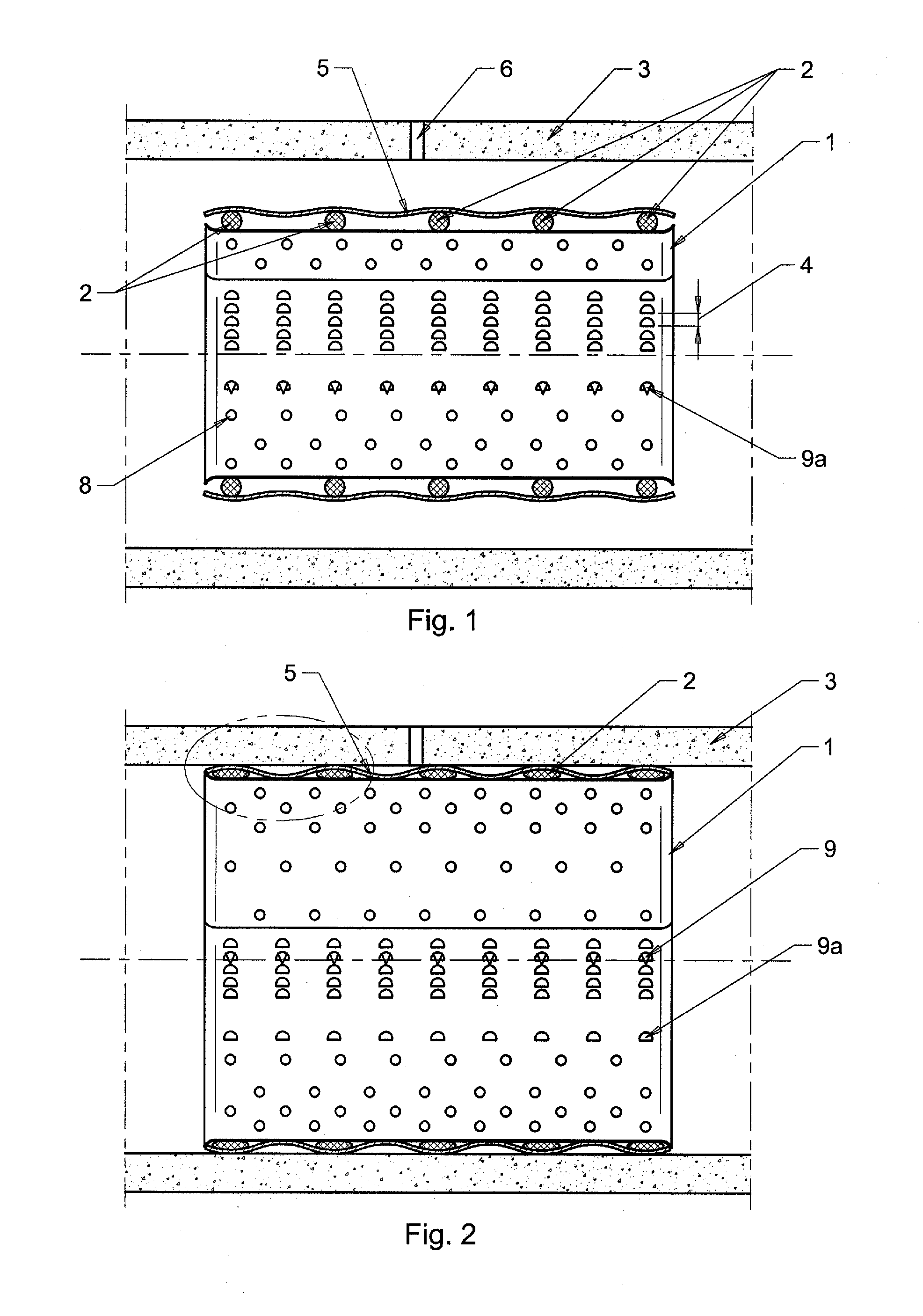
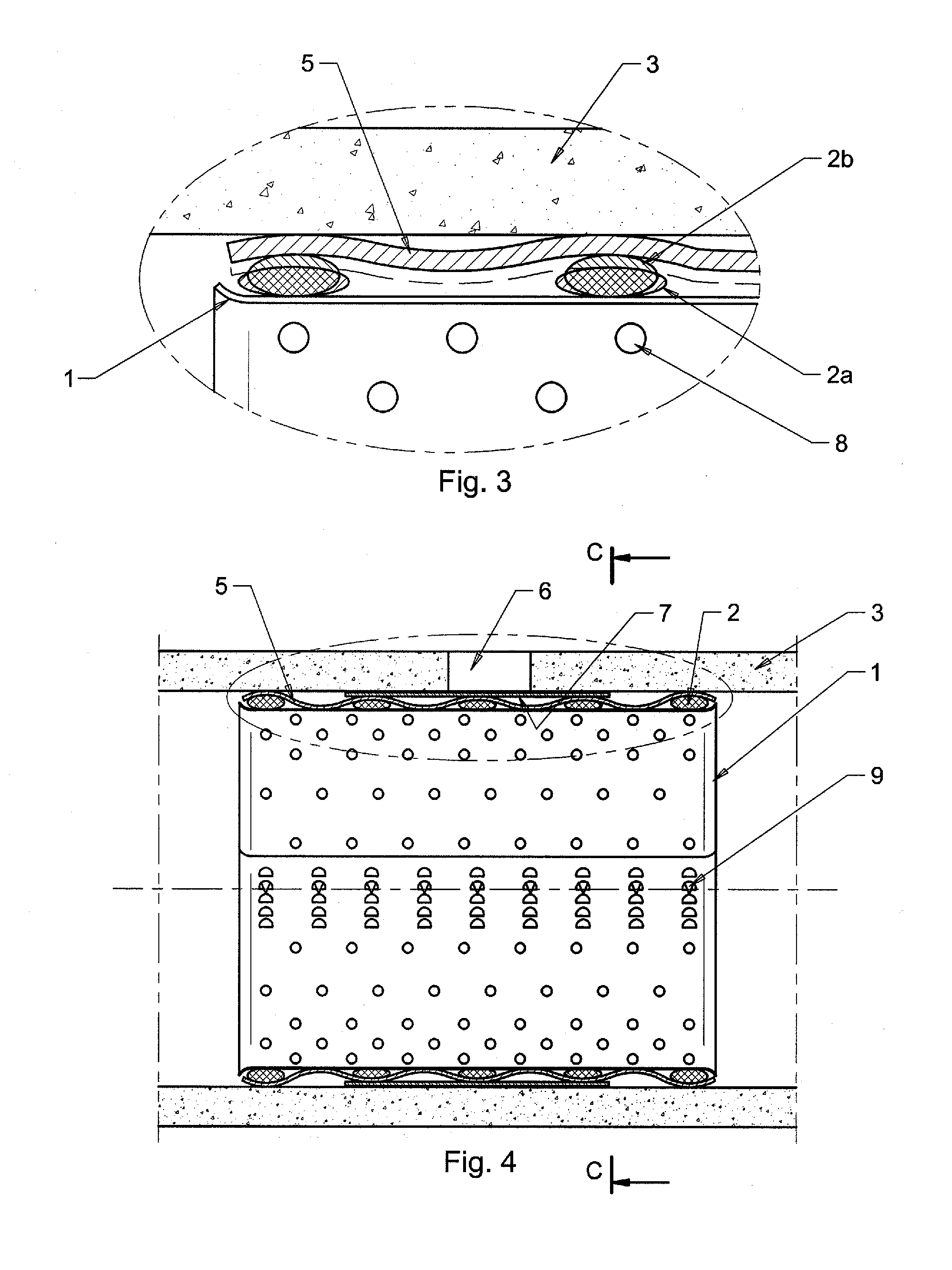
[0045]FIG. 1 shows a repair apparatus in the over-coiled pre-installation configuration. The apparatus for internal repair pipes and conduits in accordance with this invention comprises of an expandable core 1, having perforations 8 and equipped with a locking mechanism 9 (shown in FIGS. 2, 4, 7 and 9). The choice of core material, for instance stainless steel, is determined by the chemical regime in the pipe. Further, a number of O-rings 2, made from solid resilient, elastic material, are applied over the outer surface of the core 1. The quantity, the body diameter, and softness of the O-rings 2 depend on possible conduit 3 diameter changes with internal / external pressure and / or temperature changes. From another side, such parameters of the O-rings depend on chosen installation pressure of the apparatus and steps 4 changes in the core 1 circumference, i.e., the incremental distance between successive locked positions of the expandable core 1, if a chosen locking mechanism 9 is a st...


PUM


Abstract

An apparatus and method for internal repair of pipes and conduits, such as sewer pipes, pressurized water mains, water wells, and natural gas lines. The conduit repair apparatus includes a sleeve with locking mechanism to lock the sleeve in a tubular configuration. The sleeve is made of metallic or rigid plastic sheet having perforations. Some of the perforations are shaped like elongated slots and strips. A number of resilient O-rings are applied over the outer surface of the sleeve. A resilient membrane is applied over the O-rings. In one embodiment, a reinforcement band is used, and an additional layer of O-rings are included between the membrane and the reinforcement band.

Description

CROSS-REFERENCE TO RELATED APPLICATION[0001]This application is based upon U.S. Patent Application No. 61 / 170,921, filed on Apr. 20, 2009, the disclosure of which is hereby incorporated-by-reference thereto in its entirety and the priority of which is claimed under 35 USC 119(e).BACKGROUND OF THE INVENTION[0002]1. Field of the Invention[0003]The invention relates to methods and apparatuses for repairing conduits. More particularly, the invention is directed to methods and apparatuses for repairing damaged, weakened, or leaking conduits that are located in areas to which it is difficult to gain access, for example, sewer pipes, water mains, wells, and gas lines.[0004]2. Background Information[0005]Over a period of time, conduit systems for carrying water or wastewater become damaged, weakened, or otherwise begin to deteriorate and leak at the joints between adjacent sections. Such deterioration is caused by the settling of the surrounding earth adjacent the conduit system, by deterio...

Claims


Application Information

Patent Timeline
Patent Type & Authority Applications(United States)
IPC IPC(8): F16L55/163F16L55/18
CPCF16L55/163
Inventor MAIMETS, LEMBITGLADSTEIN, GARRY
Owner LINK PIPE
Learn More