Apparatus and method for soldering flat work piece

a flat work piece and apparatus technology, applied in the direction of soldering apparatus, manufacturing tools,auxillary welding devices, etc., can solve the problems of no soldering apparatus employing a flow-dip method in which soldering can be carried out, increase in the cost of soldering, and the inability to solder such a printed circuit board by a different method, so as to achieve low feed rate and low consumption

Active Publication Date: 2010-10-21
FUJITSU GENERAL LTD +1
View PDF17 Cites 14 Cited by
  • Summary
  • Abstract
  • Description
  • Claims
  • Application Information

AI Technical Summary

Benefits of technology

[0019]The present invention has been made to overcome the above problems, and it is, therefore, an object of the present invention to provide a flow-dip soldering apparatus which can carry out flow-dip soldering at a low feed rate, that is, with low consumption, of an inert gas such as nitrogen gas.
[0020]Another object of the present invention is to provide a soldering apparatus which permits high quality soldering at low costs, even when electronic parts mounted on a printed circuit board have long leads or even when partial soldering using a mask plate is carried out.
[0021]It is a further object of the present invention to provide a soldering method which can carry out soldering in an inert gas atmosphere with a low oxygen concentration with high productivity.

Problems solved by technology

Therefore, there has been no soldering apparatus employing a flow-dip method in which soldering is carried out in an inert gas atmosphere, since a complicated transfer means is required to transfer the printed circuit board not only horizontally but also vertically.
A large inert gas feed rate leads to an increase in the cost of soldering.
In addition, soldering of a printed circuit board having parts with long leads mounted thereon, that is, a printed circuit board having a surface to be brought into contact with molten solder (a surface to be soldered) from which long leads protrudes cannot be carried out by the apparatus disclosed in Document 3.
Soldering of such a printed circuit board cannot be carried out by a method other than a dip or flow-dip method.
However, there is no soldering apparatus employing a flow-dip method which can carry out soldering in an inert gas atmosphere with a low oxygen concentration at a low cost for the same reason as described above.
However, there is no soldering apparatus which can carry out soldering by a flow-dip method in an inert gas atmosphere with a low oxygen concentration for the same reason as described above.
Therefore, the soldering of such connectors yields low productivity.
(1) The mechanism of the system is so complicated that adjustment of the mechanism or recovery from a failure takes a significant amount of time, resulting in low productivity.
(2) Since different types of tubes must be used for different types of printed circuit boards to be soldered and it takes long time (about 60 minutes) to exchange the tubes. Thus, the downtime of the soldering apparatus is long, resulting in low productivity.
(3) Since there are many tubes, it takes long time (about 30 minutes, for example) to clean the tubes, resulting in low productivity.
(4) The tubes are very expensive (about one million yen per one tube, for example).
(5) It is difficult to perform the soldering in an inert gas atmosphere in a simple manner.

Method used


Image

  • Apparatus and method for soldering flat work piece
  • Apparatus and method for soldering flat work piece
  • Apparatus and method for soldering flat work piece

Examples


Embodiment Construction

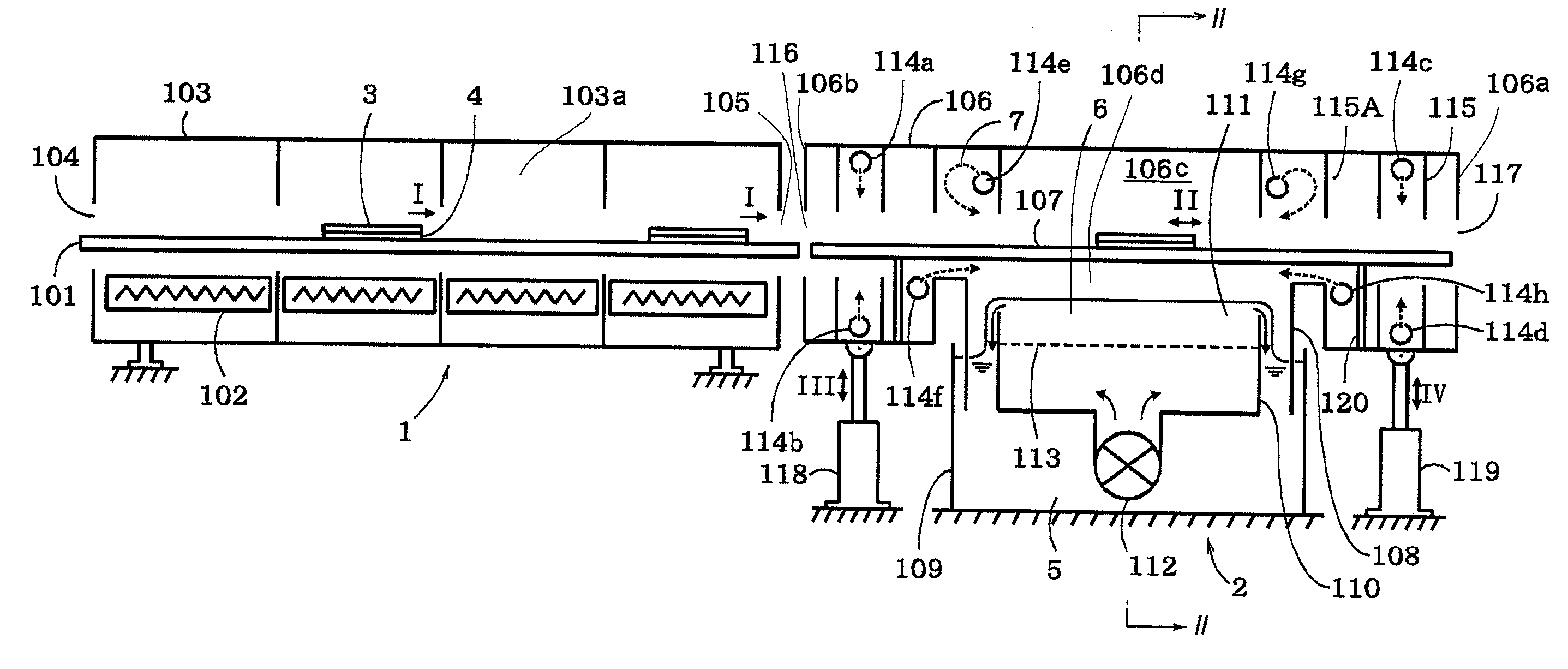
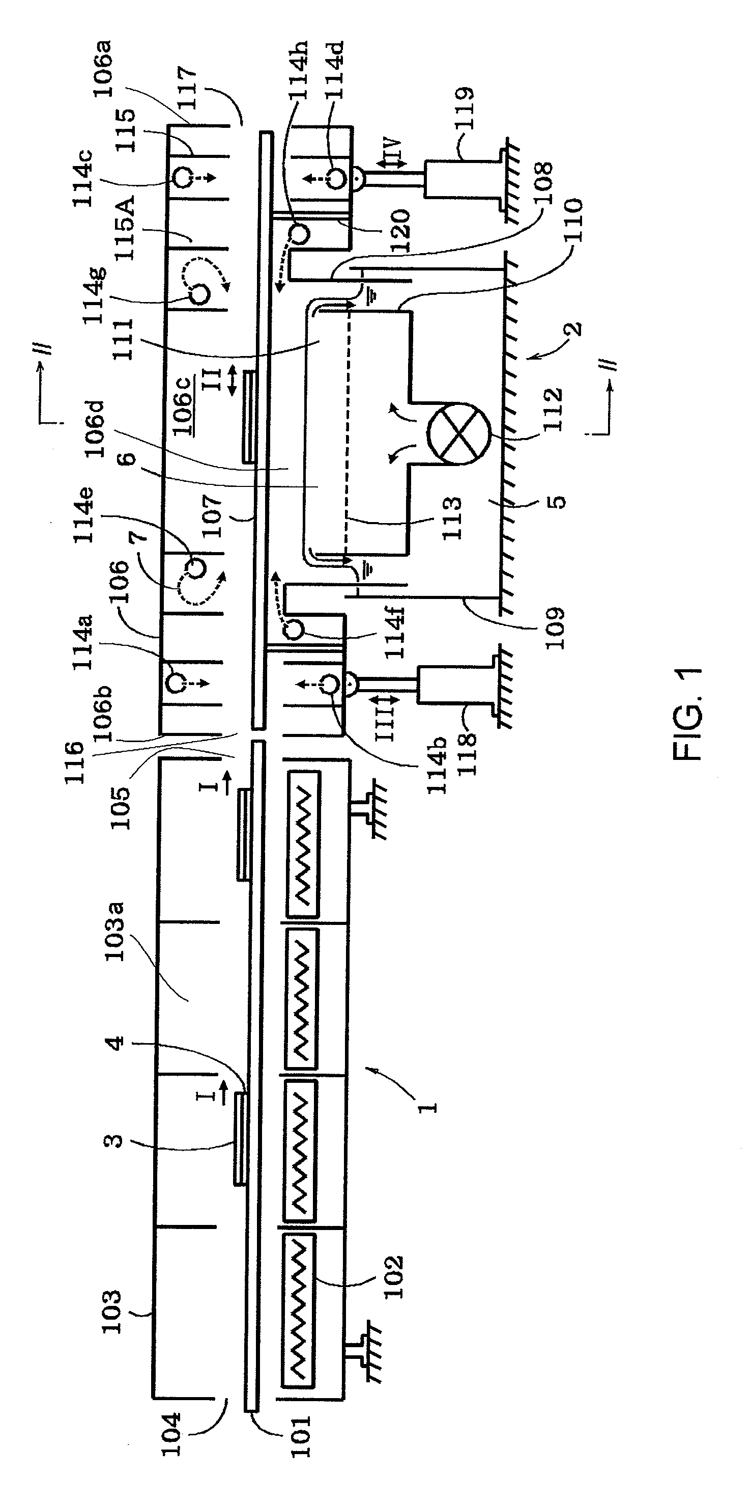
[0051]A soldering apparatus according to the present invention is adapted to carry out flow-dip soldering of a flat work piece in an atmosphere of an inert gas and is implemented as follows. In general, a soldering process includes a flux applying step, a preheating step and a soldering step as well known in the art. In the following, the description is focused mainly on the soldering step, to which the constitution of the present invention is applied.

[0052]As shown in FIG. 1, the soldering apparatus of this embodiment has a preheating section 1 and a soldering section 2.

[0053]The preheating section 1 has a case 103 defining therewithin a preheating chamber 103a. The case 103 is a means for promoting uniform preheating of a printed circuit board 3 as a work piece to be soldered and has an inlet opening 104 and an outlet opening 105.

[0054]The preheating chamber 103a is divided into four heating zones each having a heater 102 using infrared rays, hot air or a combination of such heati...


PUM

PropertyMeasurementUnit
dimensionaaaaaaaaaa
feed rateaaaaaaaaaa
volumeaaaaaaaaaa

Abstract

A soldering apparatus including a vessel containing a molten solder, a casing defining therewithin a soldering chamber in which a flat overflowing wave of the molten solder is formed, a conveyor physically integrated with the casing for movement therewith and operable for transferring a printed circuit board through the soldering chamber, actuators and for vertically moving the casing, inert gas feeders for feeding an inert gas to the soldering chamber, and a controller for controlling the operation of the actuators and, so that the printed circuit board is contacted with the surface of the flat overflowing wave in an atmosphere of the inert gas during its passage through the soldering chamber.

Description

TECHNICAL FIELD[0001]The present invention relates to apparatus and method for soldering a flat work piece by a flow dip method in which the work piece is brought into contact with a flat overflowing wave.BACKGROUND ART[0002]As methods for soldering a printed circuit board having electronic parts such as leads and terminals mounted thereon, various methods, such as a flat dip method, a dual pot method, a flow method, a wave method, a double wave method, a flow-dip method and a cascade method, are known for supplying a molten solder onto the electronic parts to be soldered and the soldering lands, that is, the regions to be soldered on the printed circuit board.[0003]Such soldering methods are described in “Denshi Gijutsu, extra edition of the June 1981 issue (Vol. 23, No. 7, 1981)” (Document 1). In Document 1, the flow-dip method is explained to have features of both of the flow or wave method and dip method. That is, in the flow-dip method, a molten solder in a solder vessel is cau...

Claims


Application Information

Patent Timeline
Patent Type & Authority Applications(United States)
IPC IPC(8): B23K31/02B23K3/08B23K3/06B23K1/20
CPCB23K1/08H05K3/3468B23K2201/42B23K2101/42B23K31/02
Inventor AOYAMA, NOBUYUKIIKEDO, KENSHIOKUNO, AKIRAARITA, MASATO
Owner FUJITSU GENERAL LTD
Why Eureka
Try Eureka