Controllable optical ring resonator having periodically spaced control electrodes

a control electrode and ring resonator technology, applied in the field of optical waveguides and photonic circuits, can solve the problems of affecting the resonance of the optical ring resonator, and affecting the performance of the controllable optical ring resonator

Active Publication Date: 2010-10-21
HEWLETT-PACKARD ENTERPRISE DEV LP
View PDF21 Cites 23 Cited by
  • Summary
  • Abstract
  • Description
  • Claims
  • Application Information

AI Technical Summary

Benefits of technology

[0009]In some embodiments of the present invention, a controllable optical ring resonator is provided. The controllable optical ring resonator comprises an optical waveguide having an optical path in a closed loop. The controllable optical ring resonator fur

Problems solved by technology

The change in refractive index interferes with or disrupts a resonance of the optical ring resonator.
Unfortunately, such relatively large control electrodes exhibit a relatively large capacitance.
The relatively large capacitance of such control electrodes can and does adversely affect a performance of the controllable optical ring resonator.
For example, the relatively large capacitance may limit

Method used


Image

  • Controllable optical ring resonator having periodically spaced control electrodes
  • Controllable optical ring resonator having periodically spaced control electrodes
  • Controllable optical ring resonator having periodically spaced control electrodes

Examples


Embodiment Construction

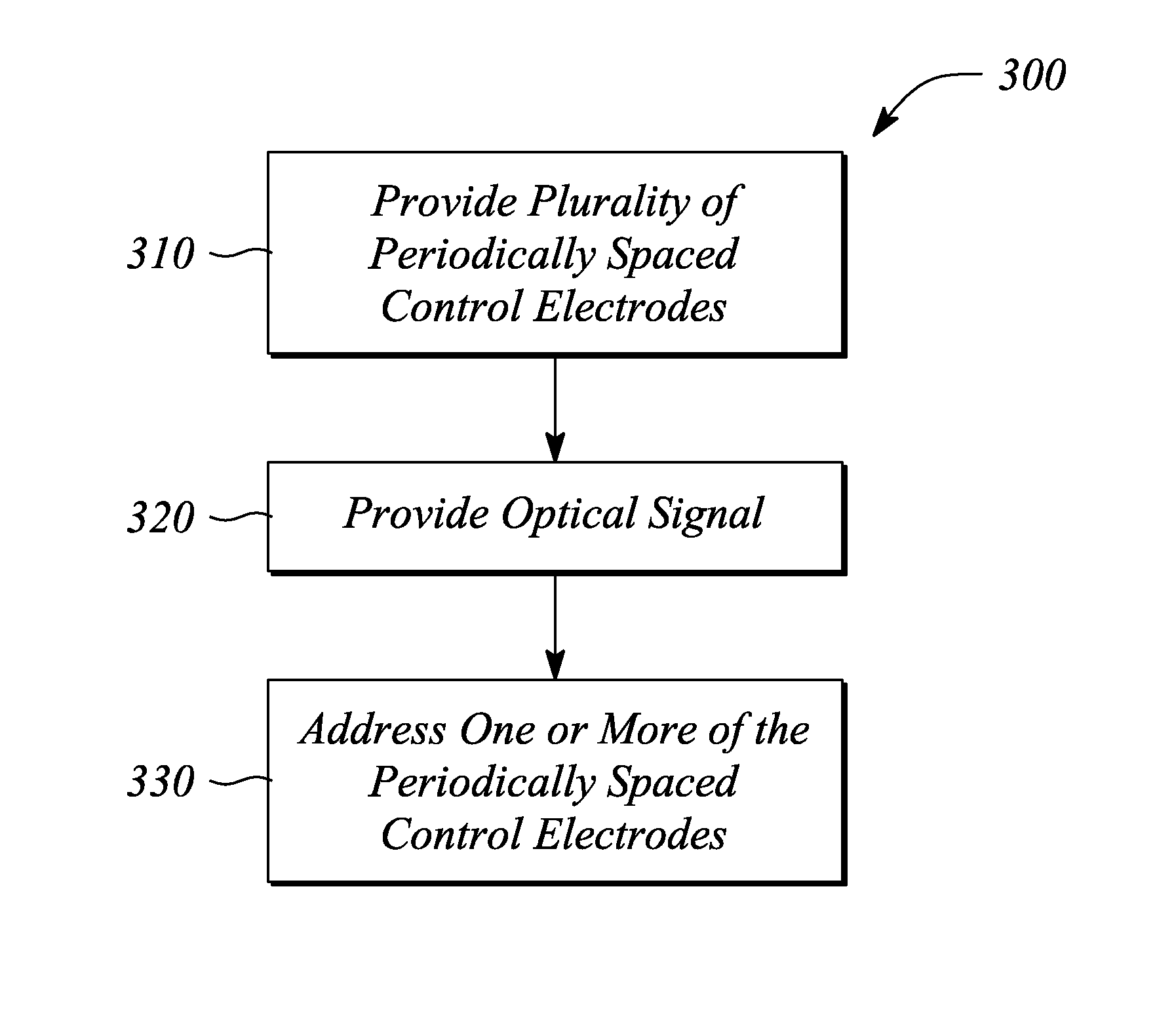
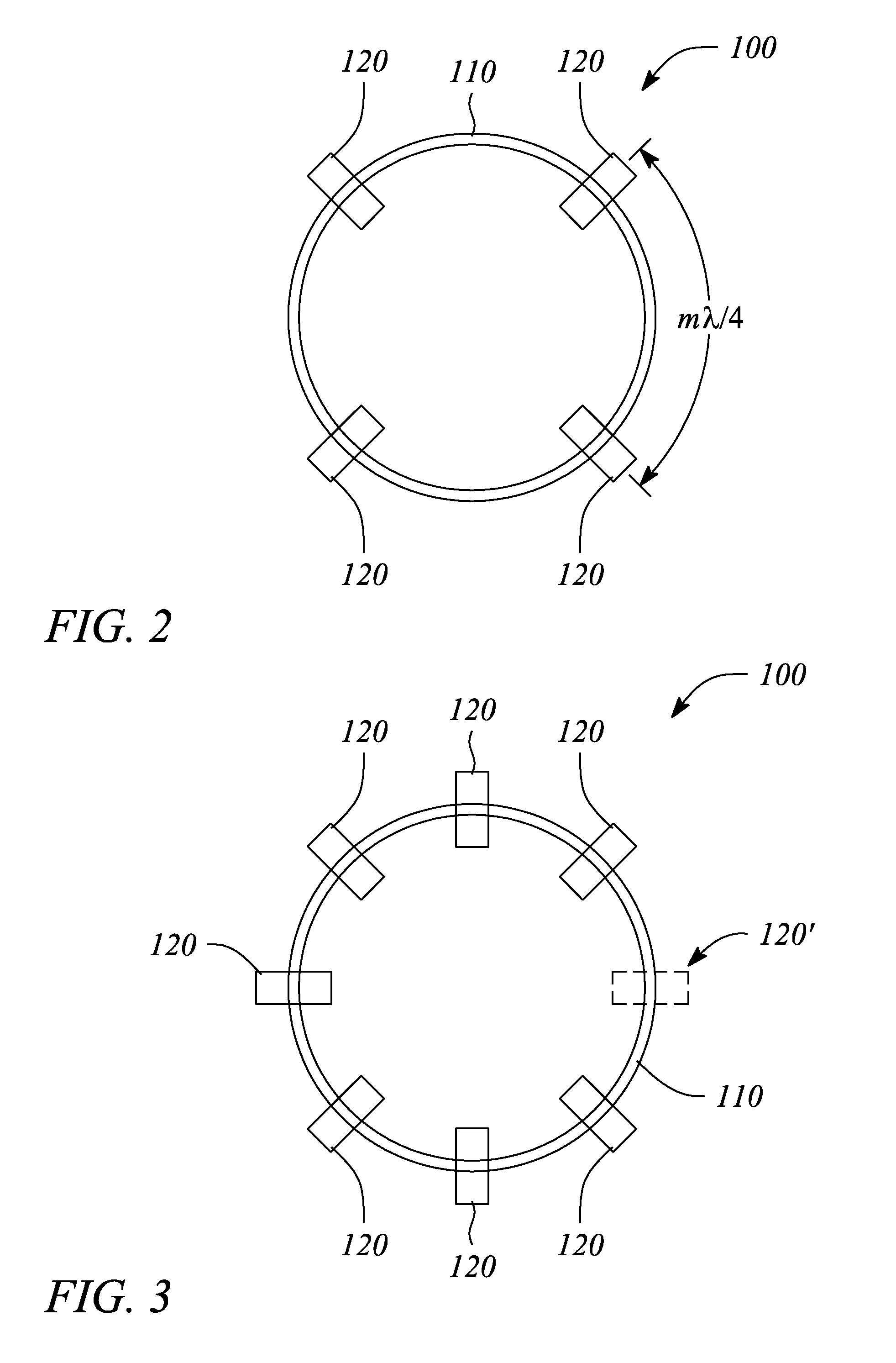
[0028]Embodiments of the present invention employ a plurality of control electrodes to control a performance of an optical ring resonator. The individual control electrodes of the plurality are periodically spaced around the optical ring resonator. In particular, the optical ring resonator according to various embodiments is a closed loop, ring-shaped resonant structure that supports a resonant optical signal within the closed loop. The plurality of periodically spaced control electrodes controls a resonance characteristic of the optical ring resonator, such that the optical ring resonator is controllable. Specifically, operation of the control electrodes interacts with the optical signal and results in effects on the overall resonance performance of the optical ring resonator. As such, various embodiments of the present invention essentially provide a controllable optical ring resonator.

[0029]In various embodiments, the plurality of periodically spaced control electrodes may exhibi...


PUM


Abstract

A controllable optical ring resonator, a photonic system and a method of controlling an optical ring resonator employ control electrodes periodically spaced apart along a closed loop optical path of an optical waveguide. The controllable optical ring resonator includes the optical waveguide and a plurality of the periodically spaced control electrodes. The photonic system includes an input optical waveguide segment and the controllable optical ring resonator adjacent and optically coupled to the segment. The method includes providing the plurality of periodically spaced control electrodes, providing an optical signal within the optical path, and addressing one or more of the control electrodes to interact with the optical signal within the optical path.

Description

CROSS-REFERENCE TO RELATED APPLICATIONS[0001]N / ASTATEMENT REGARDING FEDERALLY SPONSORED RESEARCH OR DEVELOPMENT[0002]N / ABACKGROUND[0003]1. Technical Field[0004]The invention relates to optical waveguides and photonic circuits. In particular, the invention relates to optical waveguide ring resonators used in photonic systems.[0005]2. Description of Related Art[0006]An optical ring resonator generally comprises a segment or segments of optical waveguide arranged as a ring-shaped, closed loop. Such optical ring resonators have a variety of important uses in photonic systems. For example, the optical ring resonator may be part of a photonic filter. In another example, the optical ring resonator may be employed as an element in a photonic frequency multiplexer used to select a particular frequency portion of an input optical signal. The frequency multiplexer may further route the selected frequency portion along an optical path that differs from that of the input optical signal. If the o...

Claims


Application Information

Patent Timeline
IPC IPC(8): G02F1/025
CPCG01C19/721G02F1/3132G02F2203/15
Inventor MORRIS, TERREL L.TAN, MICHAEL R.WU, WEIWANG, SHIH-YUAN
Owner HEWLETT-PACKARD ENTERPRISE DEV LP
Why Eureka
Try Eureka