Eureka AIR delivers breakthrough ideas for toughest innovation challenges, trusted by R&D personnel around the world.

Production of Saturated Ammonia Storage Materials

Inactive Publication Date: 2010-10-21
AMMINEX EMISSIONS TECH
View PDF6 Cites 6 Cited by
  • Summary
  • Abstract
  • Description
  • Claims
  • Application Information

AI Technical Summary

Benefits of technology

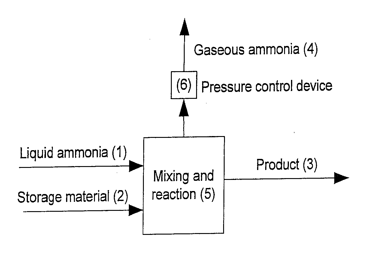
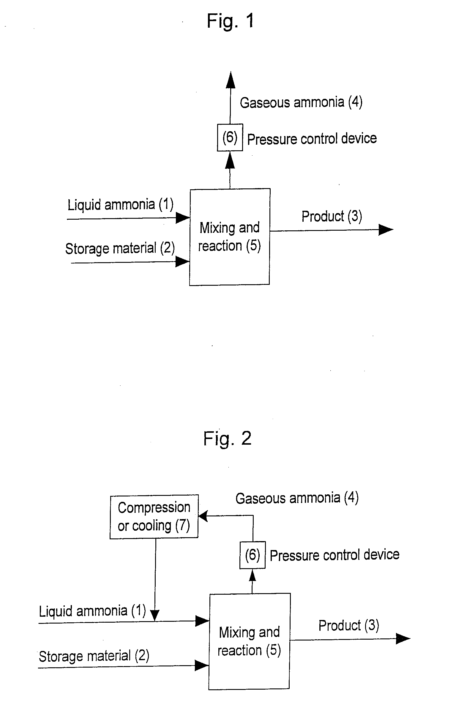
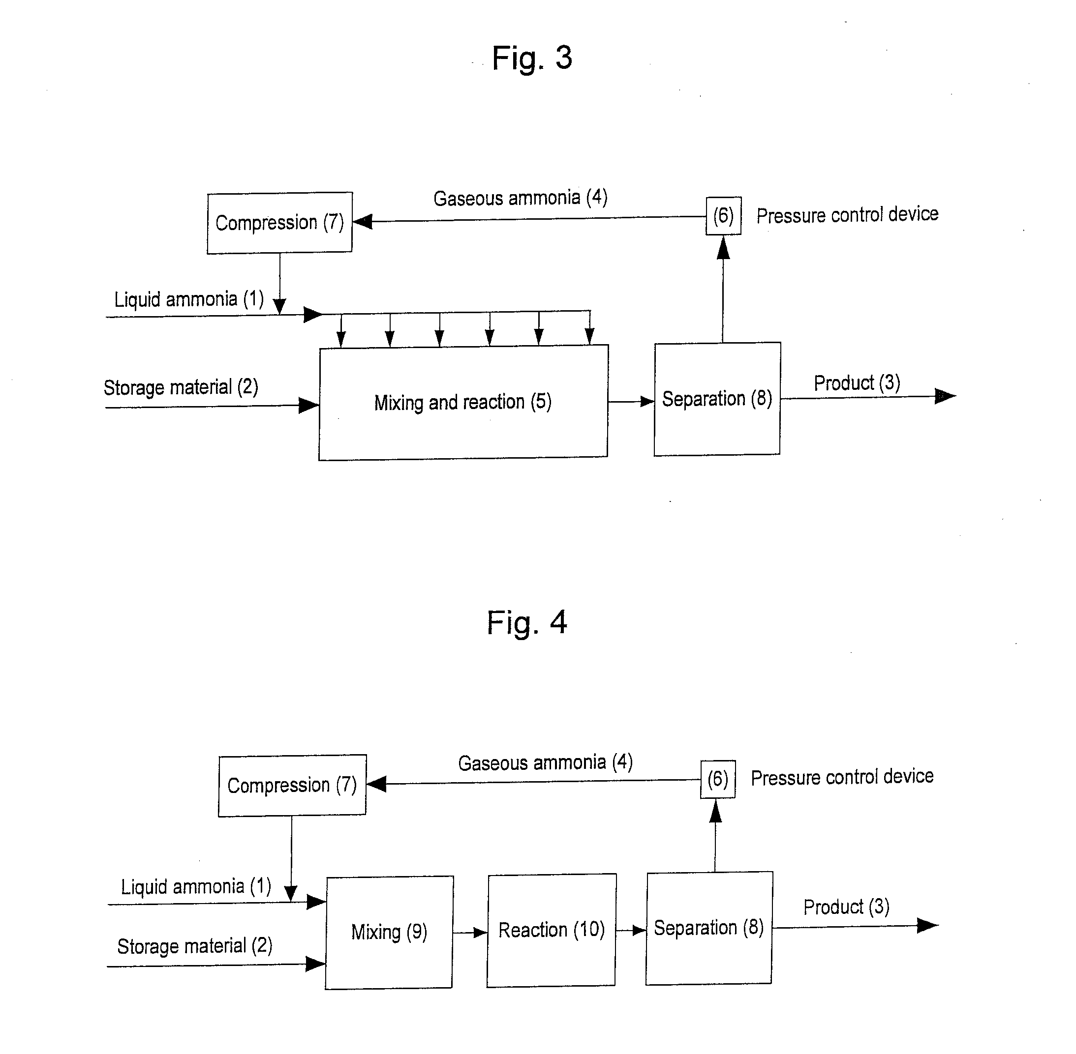
[0010]The invention relates to a process for saturating a material capable of binding ammonia by ad- or absorption and initially free of ammonia or partially saturated with ammonia, characterized in that the process comprises treating said material under a pressure and associated temperature located on the vapor pressure curve of ammonia with an amount of liquid ammonia sufficient to saturate said material and an additional amount of a cooling agent selected from liquid ammonia, liquid or solid CO2, hydrocarbons and hydrohalocarbons that have a vapour pressu

Problems solved by technology

For most applications, and in particular in automotive applications, the storage of ammonia in the form of a pressurized liquid in a vessel is too hazardous.
Urea is a safe, but an indirect and impractical method for mobile transport of ammonia since it requires to be transformed into ammonia by a process involving thermolysis and hydrolysis ((NH2)2CO+H2O→2 NH3+CO2).
This method is slow (for example saturating 3 kg SrCl2 with 6 bar pressure of ammonia takes 3 days).
This method only works for materials that are easily dissolvable in liquid ammonia (which for example is not the case for the attractive storage material SrCl2) and is inefficient since large amounts of excess ammonia have to be evaporated.

Method used


Image

  • Production of Saturated Ammonia Storage Materials
  • Production of Saturated Ammonia Storage Materials
  • Production of Saturated Ammonia Storage Materials

Examples


example 1

[0057]One mole SrCl2 can bind r=8 mole of NH3 as Sr(NH3)8Cl2. The average absorption energy of ammonia in SrCl2 is Ēa=42.2 kJ / mole. 1000 kg of SrCl2 with a molar mass of 158.5 g / Mole corresponds to n=6.4×10³ mole that can bind ms=50.5×10³ mole of NH3. The amount of NH3 needed for removal of excess heat is then

me=msE_a-EeEe=40.5×10³

mole of NH3. The total minimum amount of ammonia needed for the process is then mtot=91×103 mole or 1550 kg.

[0058]If the same calculation was done for CaCl2, the result would be in the same range, since the binding energy of ammonia to CaCl2 is similar to that of SrCl2. For MgCl2, the average absorption energy is approximately Eb=65 kJ / mole, which gives considerably higher mass of ammonia needed to be supplied to the saturation process to balance the higher heat release per ammonia molecule from the formation of Mg(NH3)6Cl2 compared to Sr(NH3)8Cl2.

example 2

[0059]In one experiment 3 kg of SrCl2 is saturated with ammonia in a rotating vessel. A total amount of ammonia of 4.65 kg is dosed into the system at a rate 150 g / min at a vessel pressure of 8 bar. The salt is saturated to more than 95% within 35 minutes. The reactor temperature is close to room temperature at all times.

example 3

[0060]Example 3 is similar to Example 2 except that the total amount of ammonia is dosed within the first 2 minutes. After 25 minutes release of excess ammonia stops and the material is saturated to a degree of more than 95%.


PUM


Abstract

A process for saturating a material capable of binding ammonia by ad- or absorption and initially free of ammonia or partially saturated with ammonia comprises treating said material under a pressure and associated temperature located on the vapor pressure curve of ammonia with an amount of liquid ammonia sufficient to saturate said material and an additional amount of a cooling agent selected from liquid ammonia, liquid or solid CO2, hydrocarbons and hydrohalocarbons that have a higher vapour pressure than ammonia, ethyl ether, methyl formate, methyl amine and ethyl amine, such that |Qabs|≦|Qevap|+Qext, wherein Qabs is the amount of heat released from said material when it absorbs ammonia from the liquid phase thereof to the point where it is saturated with ammonia, Qevap is the amount of heat absorbed by said cooling agent when it evaporates, and Qext is the amount of heat exchanged with the surroundings and is positive, if heat is removed from the process by external cooling, and negative, if heat is added to the process from the surroundings.

Description

[0001]This application is based upon and claims priority from U.S. Provisional Application Ser. No. 61 / 169,776, filed Apr. 16, 2009, incorporated herein by reference. This invention relates to a method for saturating materials capable of binding ammonia with ammonia and particularly to the production of ammonia containing metal ammine salts of the general form Ma(NH3)rXz.FIELD OF THE INVENTIONBackground of the Invention[0002]Ammonia is a widely used chemical with many applications. One specific application is as reductant for selective catalytic reduction (SCR) of NO in exhaust gas from combustion processes.[0003]For most applications, and in particular in automotive applications, the storage of ammonia in the form of a pressurized liquid in a vessel is too hazardous. Urea is a safe, but an indirect and impractical method for mobile transport of ammonia since it requires to be transformed into ammonia by a process involving thermolysis and hydrolysis ((NH2)2CO+H2O→2 NH3+CO2).[0004]A...

Claims


Application Information

Patent Timeline
IPC IPC(8): C01C1/00
CPCC01C1/006C01F11/24C01F5/30
Inventor JOHANSEN, JOHNNYWAGNER-PEDERSEN, HENRIKSVAGIN, JAKOBJOHANNESSEN, TUEQUAADE, ULRICH J.
Owner AMMINEX EMISSIONS TECH
Why Eureka
Eureka Blog
Learn More