Fluorescence imaging apparatus and endoscope apparatus

a fluorescence imaging and endoscope technology, applied in fluorescence/phosphorescence, optical radiation measurement, spectrometry/spectrophotometry/monochromators, etc., can solve the problems of fluorescence intensity, fluorescence image darkening, and becomes even weaker, so as to reduce the size of the endoscope apparatus, reduce the pain inflicted, and observe the subject easily

Inactive Publication Date: 2010-10-21
OLYMPUS CORP
View PDF11 Cites 21 Cited by
  • Summary
  • Abstract
  • Description
  • Claims
  • Application Information

AI Technical Summary

Benefits of technology

[0010]The present invention has been conceived in light of the circumstances described above, and an object thereof is to provide a fluorescence imaging apparatus and endoscope apparatus that are capable of easily performing observation under bright excitation light in the case where a lesion etc. is to be identified while observing a wide area of a subject, and also in the case where the distal end of the fluorescence imaging apparatus is brought close to the subject to perform detailed observation.
[0022]According to the aspects described above, an advantage is afforded in that it is possible to easily perform observation under bright excitation light in the case where a lesion etc. is to be identified while observing a wide area of the subject, and also in the case where the distal end of the fluorescence imaging apparatus is brought close to the subject to perform detailed observation.

Problems solved by technology

However, when the distal end is away from the surface of the observation site, because the intensity of the excitation light decreases in inverse proportion to the square of the distance, the fluorescence intensity, which is already weak to begin with, becomes even weaker, causing the fluorescence image to darken and making it difficult to discern the lesion etc.
One way that has been considered is to increase the output of the light source to increase the intensity of the excitation light; however, the power consumption is greatly increased, and there are limits to the intensity of excitation light that can be emitted, depending on the capacity of the light source.
Another solution that has been considered is to adjust the fluorescence imaging brightness by changing the characteristics of the filter etc. for fluorescence detection; however, when an image-acquisition unit is provided at the distal end of an observation apparatus, as in an electronic endoscope, because the fluorescence detection filter etc. is also disposed at the distal end of the observation apparatus, it is difficult to change the filter characteristics during observation.

Method used


Image

  • Fluorescence imaging apparatus and endoscope apparatus
  • Fluorescence imaging apparatus and endoscope apparatus
  • Fluorescence imaging apparatus and endoscope apparatus

Examples


first embodiment

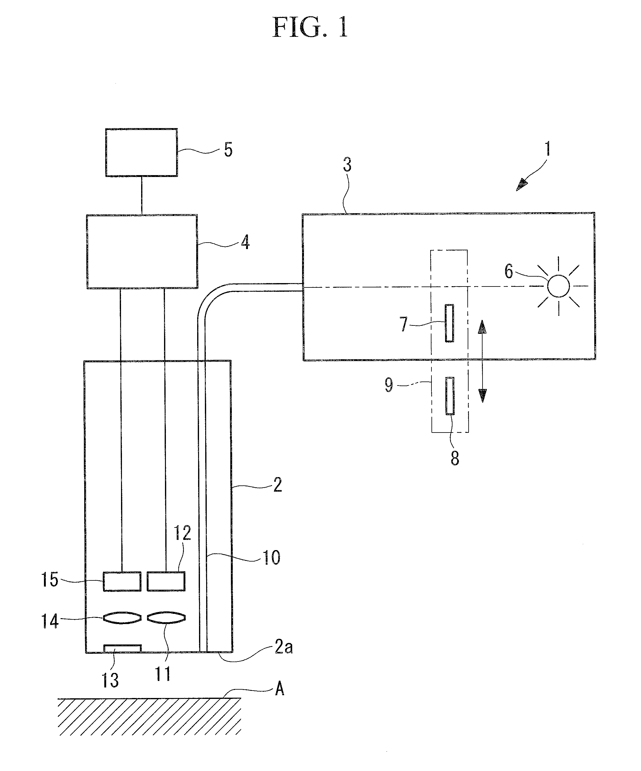
[0030]A fluorescence apparatus 1 according to the present invention will be described below with reference to FIG. 1 and FIG. 2.

[0031]As shown in FIG. 1, the fluorescence imaging apparatus 1 according to this embodiment, which is an endoscope apparatus, includes a long, narrow inserted portion 2 that is inserted inside the body cavity of a patient, a light-source apparatus 3 and an image processing apparatus 4 that are connected to the inserted portion 2 and disposed outside the patient's body, and a display device 5 that is connected to the image processing apparatus 4 and that displays an image-processed image.

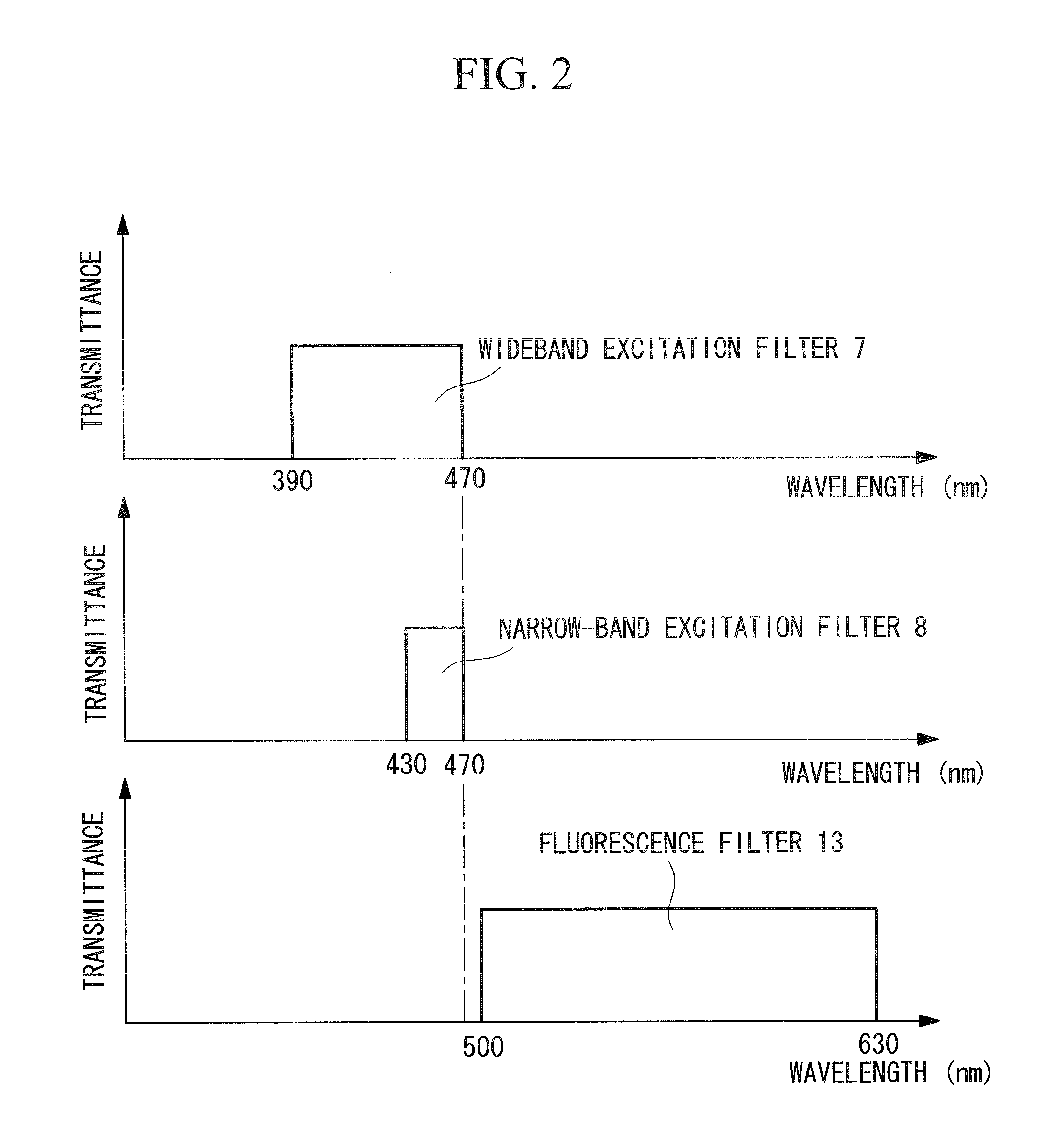
[0032]The light source apparatus 3 includes a white-light source 6 such as a xenon lamp, a wideband excitation filter 7 that transmits excitation light in a wavelength band of 370 to 470 nm among the white light emitted from the white-light source 6, a narrow-band excitation filter 8 that transmits excitation light in a wavelength band of 430 to 470 nm, and an excitation-ban...

second embodiment

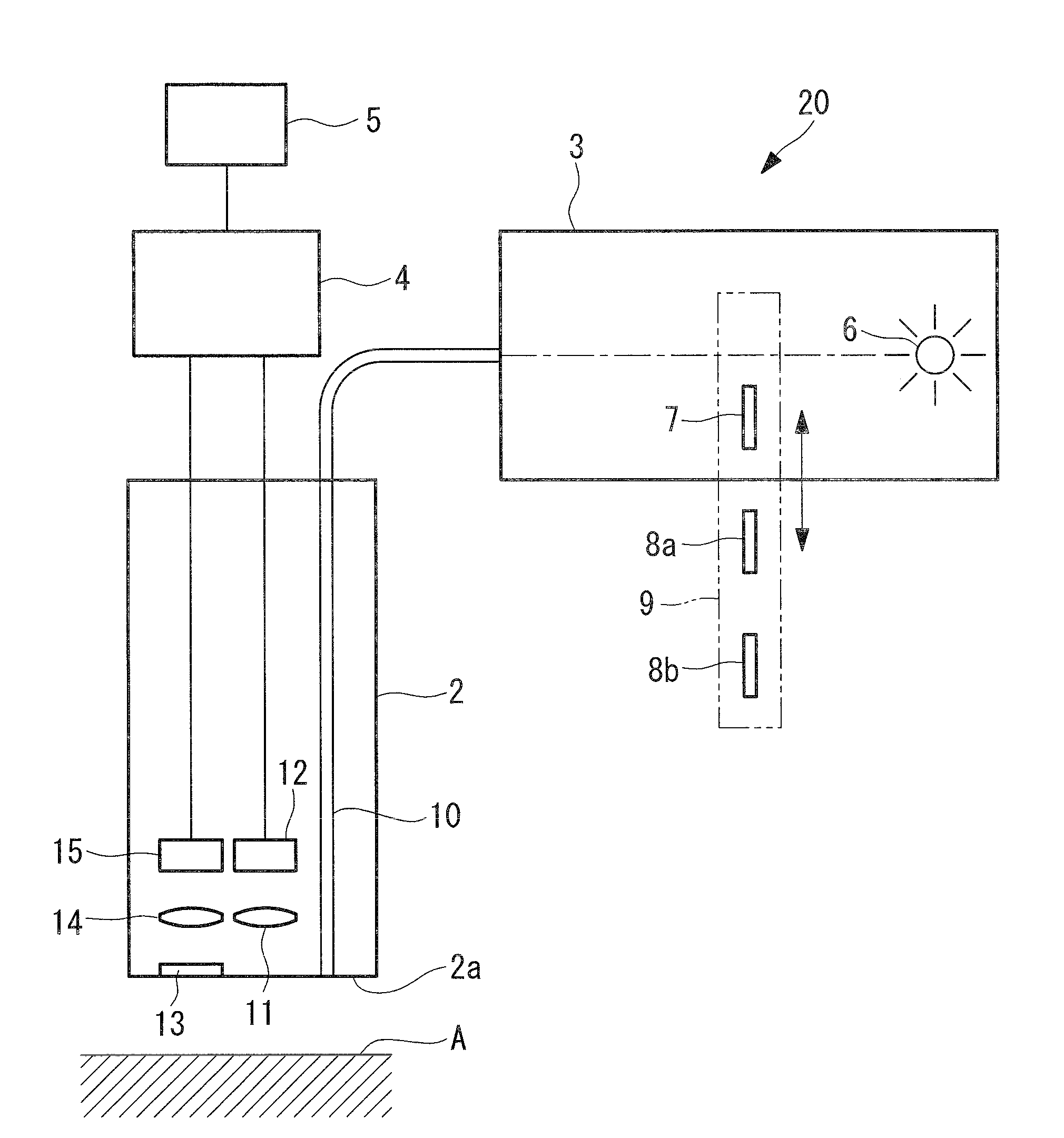
[0054]Next, a fluorescence imaging apparatus 20 according to the present invention will be described with reference to FIGS. 3 and 4.

[0055]In the description of this embodiment, parts having the same construction as those in the fluorescence imaging apparatus 1 according to the first embodiment described above are assigned the same reference numerals, and a description thereof will be omitted.

[0056]As shown in FIG. 3, the fluorescence imaging apparatus 20 according to this embodiment differs from the fluorescence imaging apparatus 1 according to the first embodiment in that two narrow-band excitation filters 8a and 8b are provided.

[0057]The fluorescence imaging apparatus 20 according to this embodiment includes a wideband excitation filter 7 having a wavelength band of 390 to 600 nm, a narrow-band excitation filter 8a having a wavelength band of 390 to 430 nm, and a narrow-band excitation filter 8b having a wavelength band of 560 to 600 nm. The transmission wavelength band of the fl...


PUM


Abstract

A site to be observed, such as a lesion, is easily observed by means of bright fluorescence images without increasing the output of a light source. Provided is a fluorescence imaging apparatus (1) including a wideband excitation portion (7) that radiates wideband excitation light capable of exciting a plurality of fluorescent substances contained in a subject (A); a narrow-band excitation portion (8) that radiates narrow-band excitation light capable of exciting at least one fluorescent substance among the fluorescent substances; an excitation-band switching unit (9) that performs switching between the wideband excitation portion (7) and the narrow-band excitation portion (8); and a fluorescence detector (15) having a detection wavelength band enabling detection of any kind of fluorescence from the subject (A) caused by the wideband excitation light and the narrow-band excitation light.

Description

TECHNICAL FIELD[0001]The present invention relates to fluorescence imaging apparatuses and endoscope apparatuses.BACKGROUND ART[0002]Known fluorescence imaging apparatuses in the related art observe agent fluorescence produced by administering a fluorescent agent to an observation site in a living organism and exciting the fluorescent agent (for example, see Patent Citation 1).[0003]In order to remove noise contained in the observed fluorescence due to the shape of the living organism, the distance between the fluorescence imaging apparatus and the living organism, and so forth, this fluorescence imaging apparatus irradiates the observation site in the living organism with excitation light in an excitation wavelength band capable of exciting the fluorescent agent and an autofluorescent substance, detects all fluorescence components emitted from the observation site and a fluorescence component with a wavelength band in part of the wavelength band of the agent fluorescence, and divid...

Claims


Application Information

Patent Timeline
Patent Type & Authority Applications(United States)
IPC IPC(8): A61B1/06G01J1/58A61B6/00
CPCA61B1/0005A61B1/00096A61B1/043A61B1/05A61B1/0638A61B5/0071A61B1/0646G01J1/58G01J3/10G01N21/64G01N21/6456A61B1/00186A61B1/063A61B5/0084
Inventor TAKAOKA, HIDEYUKI
Owner OLYMPUS CORP
Why Eureka
Try Eureka