
Continuous batch tunnel washer and method

a technology of tunnel washers and washers, which is applied in the direction of other washing machines, textile treatment, textiles and paper, etc., can solve the problems of reducing the effectiveness and dilution of washing chemicals, and achieve the effect of ensuring the affectiveness of high velocity counterflow, high rinsing efficiency and increasing chemical intensity

Active Publication Date: 2010-10-28
PELLERIN MILNOR
View PDF19 Cites 10 Cited by
  • Summary
  • Abstract
  • Description
  • Claims
  • Application Information

AI Technical Summary

Benefits of technology

[0015]The present invention thus provides a continuous batch washer tunnel washer apparatus that achieves very low water consumption and greater throughput. For example, typical water consumption is between about 0.3-0.36 gallons per pound (2.4-3.0 liters per kilogram) for light to medium soil and between about 0.42 and 0.6 gallons per pound (3.5-5.0 liters per kilogram) for heavy soil.
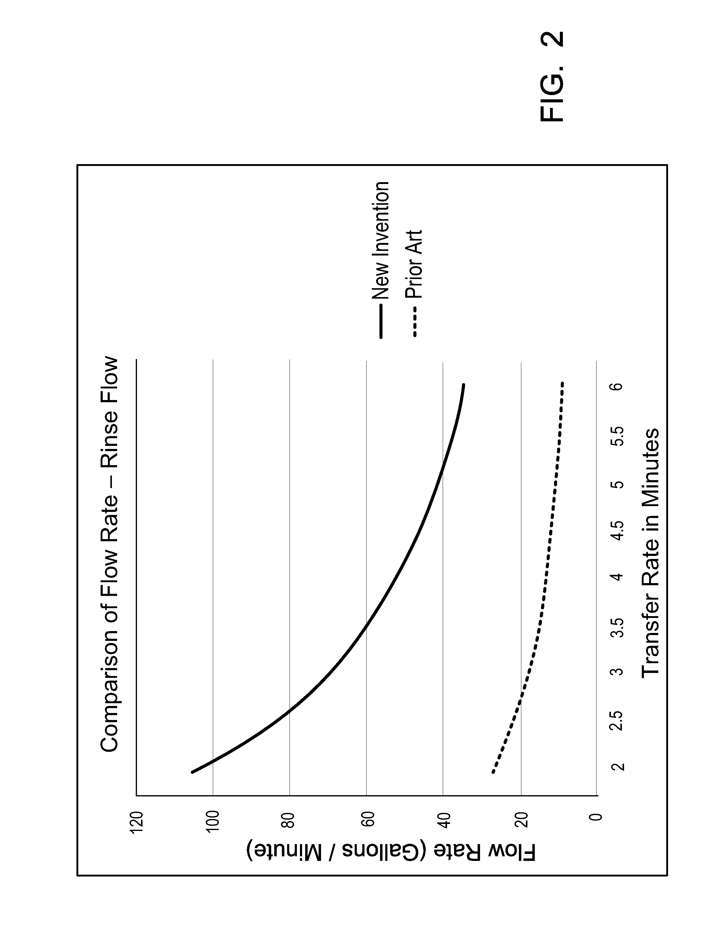
[0026]In one embodiment, a recirculation pump flows water in a recirculation loop from the bottom of a first module's shell into the linen loading chute. By using the module's own water instead of fresh water, this device reduces the overall water consumption by approximately 1 L / Kg. The recirculation pump flows at a rate of between 60 and 100 gallons per minute (g.p.m.) (227 and 379 liters per minute) to provide a forceful stream of water. This forceful stream of water wets the entire load of linen in one cylinder reversal of approximately ten (10) seconds where prior art needed the entire transfer rate time, normally between one and one half and three (1.5 to 3) minutes. Thus, most of the transfer rate time in the first module can now be used as a working module where prior art tunnel washers or continuous batch washers used the first module only to wet the linen. Thus, the production rate of the continuous batch washer or CBW is increased between five and twenty (5 and 20) percent.

Problems solved by technology

This practice dilutes the washing chemical and reduces its effectiveness.

Method used


Image

  • Continuous batch tunnel washer and method
  • Continuous batch tunnel washer and method
  • Continuous batch tunnel washer and method

Examples


Embodiment Construction

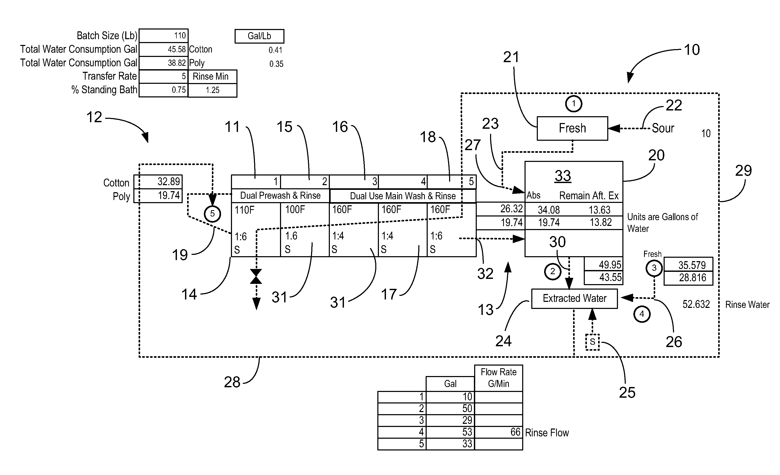
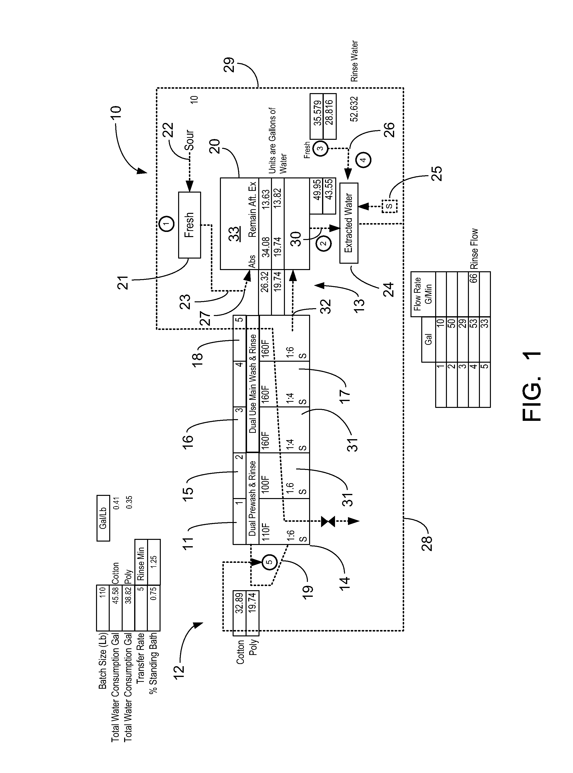
[0036]FIG. 1 shows a schematic diagram of the textile washing apparatus of the present invention, designated generally by the numeral 10. Textile washing apparatus 10 provides a continuous batch washer or tunnel washer 11 having an inlet end portion 12 and an outlet end portion 13.

[0037]In FIG. 1, tunnel washer 11 provides a number of modules, sections or zones 14-18. These modules 14-18 can include a first module 14 and a second module 15 which can be pre-wash modules 14, 15. The plurality of modules 14-18 can also include modules 16, 17 and 18 which can be dual use modules in that the modules 16, 17, 18 function as both main wash and rinse modules. Modules 14-18 could all be dual use modules. For example, modules 14, 15 could function as pre-wash modules, modules 16, 17, 18 could function as main wash modules and all modules 14-18 could function as rinse modules. For “pre-wash” modules 14 and / or 15 a desired pre-wash chemical could be added to those modules. A main wash chemical c...


PUM


Abstract

A method of washing fabric articles in a tunnel washer includes moving the fabric articles from the intake of the washer to the discharge of the washer through first and second sectors that are a pre-wash zone. Liquid can be counter flowed in the wash interior along a flow path that is generally opposite the direction of travel of the fabric articles. The main wash zone can be heated as an option. In the wash zone, there is a pre-rinse and / or a rinse. The fabric articles are transferred to a water extraction device that enables removal of excess water. A sour solution can be added to the fabric articles while extracting excess water.

Description

CROSS-REFERENCE TO RELATED APPLICATIONS[0001]Priority of U.S. Provisional Patent Application Ser. No. 61 / 171,682, filed 22 Apr. 2009, incorporated herein by reference, is hereby claimed. Priority of U.S. Provisional Patent Application Ser. No. 61 / 298,818, filed 27 Jan. 2010, incorporated herein by reference, is hereby claimed.STATEMENT REGARDING FEDERALLY SPONSORED RESEARCH OR DEVELOPMENT[0002]Not applicableREFERENCE TO A “MICROFICHE APPENDIX”[0003]Not applicableBACKGROUND OF THE INVENTION[0004]1. Field of the Invention[0005]The present invention relates to continuous batch washers or tunnel washers. More particularly, the present invention relates to an improved method of washing textiles or fabric articles (e.g., on clothing, linen, etc.) in a continuous batch multiple module tunnel washer wherein the textiles are moved sequentially from one module or zone to the next module or zone. These zones can include dual use zones, because the zones are used for both washing and rinsing. A...

Claims


Application Information

Patent Timeline
Patent Type & Authority Applications(United States)
IPC IPC(8): D06B1/00
CPCD06F31/005D06F35/005D06F31/00
Inventor POY, RUSSELL H.GAROFALO, SAMUEL
Owner PELLERIN MILNOR
Learn More