
Exhaust gas sensor heater degradation diagnosis device

a technology of exhaust gas sensor and diagnosis device, which is applied in the direction of electric control, combustion engines, machines/engines, etc., can solve the problems of low sensing accuracy of exhaust gas sensor, inability to detect degradation of heater b>28/b>, and achieve the effect of improving the diagnostic accuracy of heater degradation

Inactive Publication Date: 2010-10-28
DENSO CORP
View PDF5 Cites 8 Cited by
  • Summary
  • Abstract
  • Description
  • Claims
  • Application Information

AI Technical Summary

Benefits of technology

[0008]it is an object of the present invention to provide an exhaust gas sensor heater degradation diagnosis device capable of accurately diagnosing degradation of a heater based on a heater terminal voltage.
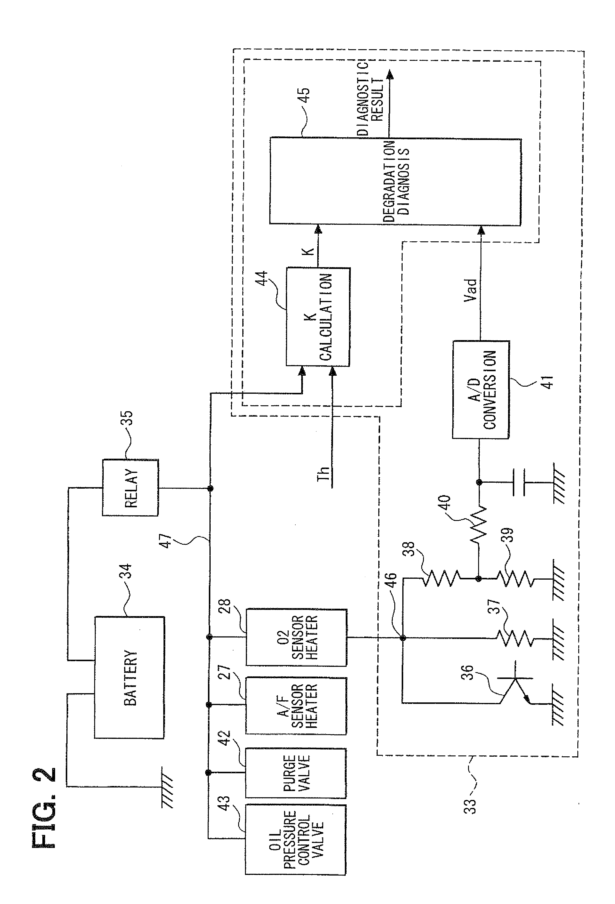
[0011]In this case, the heater terminal voltage decreases if the voltage of the battery decreases even when the heater has not degraded. Therefore, according to a second example aspect of the present invention, the degradation diagnosing section has a section for changing a determination condition for determining existence or nonexistence of the degradation of the heater in accordance with a voltage of the battery. With such the construction, the appropriate determination condition can be set by changing the determination condition in accordance with the change in the heater terminal voltage occurring in accordance with the voltage of the battery. Thus, the degradation diagnosis accuracy of the heater can be improved. When the determination condition is changed in accordance with the voltage of the battery, a degradation determination value to be compared with the heater terminal voltage information may be changed in accordance with the voltage of the battery. Alternatively, the heater terminal voltage information may be corrected in accordance with the voltage of the battery.
[0012]The resistance of the heater changes in accordance with the temperature of the heater due to a temperature characteristic of the heater, whereby the heater terminal voltage changes. Therefore, according to a third example aspect of the present invention, the degradation diagnosing section has a section for changing a determination condition for determining existence or nonexistence of the degradation of the heater in accordance with temperature of the heater. With such the construction, the appropriate determination condition can be set by changing the determination condition in accordance with the change in the heater terminal voltage caused by the change in the resistance of the heater occurring in accordance with the temperature of the heater. Thus, the degradation diagnosis accuracy of the heater can be improved.
[0013]According to a fourth example aspect of the present invention, the degradation diagnosing section has a section for prohibiting the degradation diagnosis of the heater when a voltage of the battery changes suddenly at change speed higher than predetermined speed. When the battery voltage changes suddenly, the heater terminal voltage fluctuates suddenly. Therefore, in such the case, it is determined that there is a possibility that the degradation diagnosis accuracy of the heater based on the heater terminal voltage information falls, and the degradation diagnosis of the heater is prohibited. Thus, the fall of the degradation diagnosis accuracy of the heater due to the sudden change in the battery voltage can be prevented.
[0015]Therefore, according to a fifth example aspect of the present invention, the degradation diagnosing section has a section for permitting the degradation diagnosis of the heater when an electric load that affects the electric power supplied to the heater is not operating. With such the construction, when the electric load that affects the supplied power of the heater is not in operation, it is determined that the supplied power of the heater stabilizes and the heater terminal voltage stabilizes, and the degradation diagnosis of the heater based on the heater terminal voltage information is permitted. Thus, the degradation diagnosis accuracy of the heater can be improved.

Problems solved by technology

Generally, sensing accuracy of the exhaust gas sensor is low or sensing is impossible unless temperature of a sensor element increases to activation temperature.
Accordingly, there exists a problem that the degradation of the heater 28 cannot be detected even if the heater terminal voltage is evaluated.

Method used

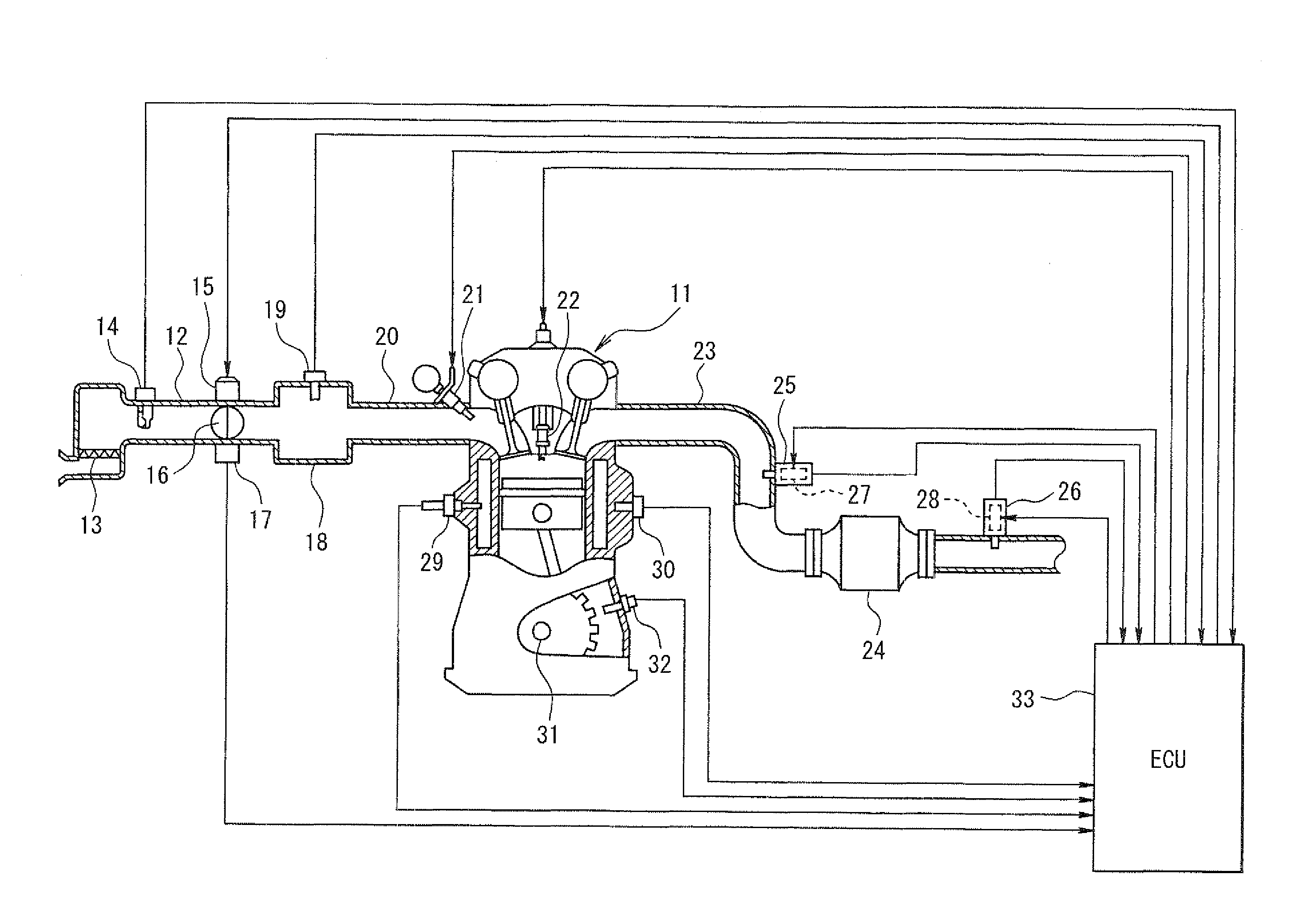

Image

  • Exhaust gas sensor heater degradation diagnosis device
  • Exhaust gas sensor heater degradation diagnosis device
  • Exhaust gas sensor heater degradation diagnosis device

Examples


Embodiment Construction

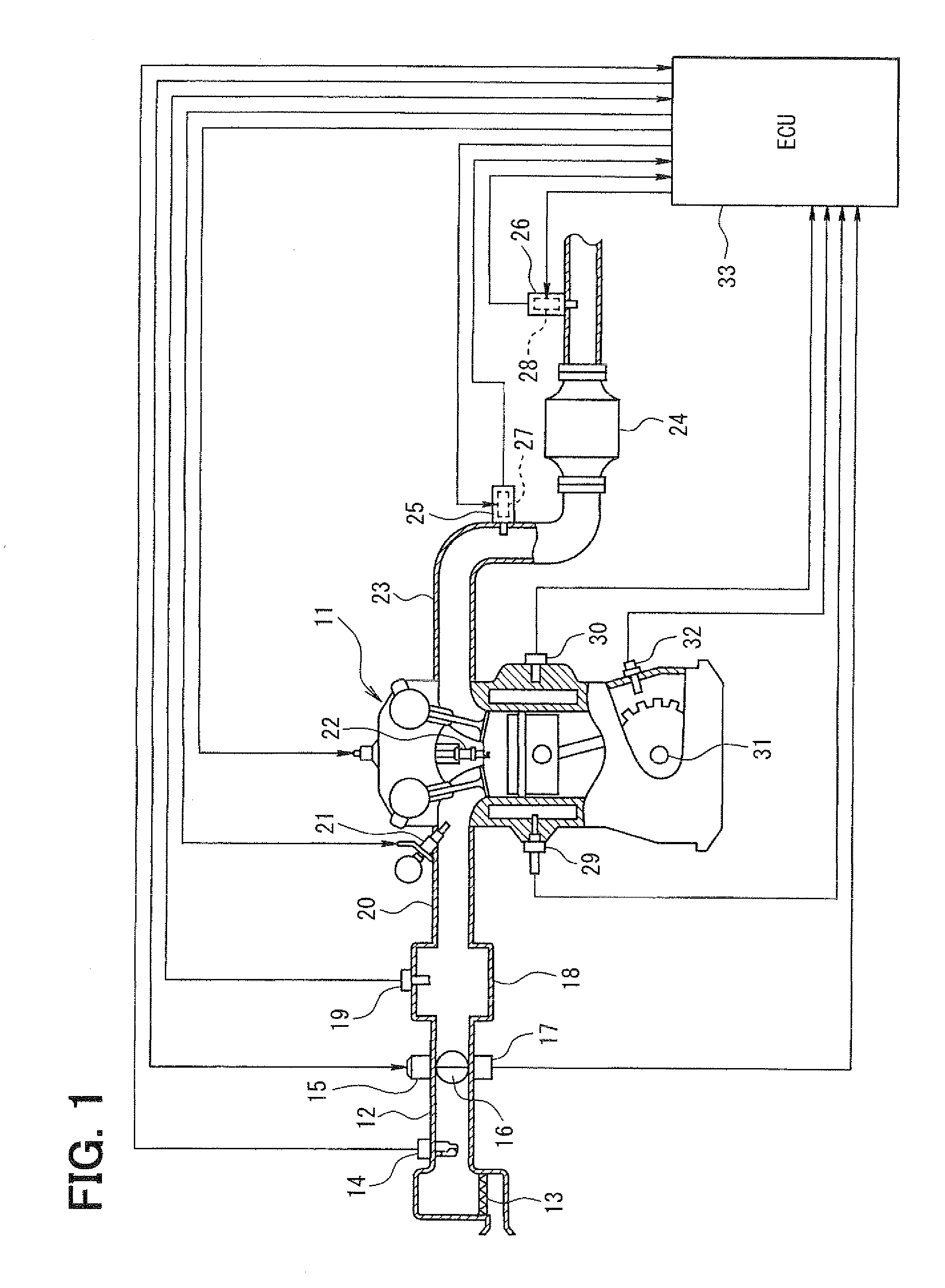
[0021]Hereafter, an embodiment of the present invention will be described with reference to the drawings. First, a general configuration of an entire engine control system according to the present embodiment will be explained with reference to FIG. 1. An air cleaner 13 is provided in the most upstream portion of an intake pipe 12 of an engine 11 (internal combustion engine). An airflow meter 14 for sensing an air intake quantity is provided downstream of the air cleaner 13. A throttle valve 16, whose opening degree is regulated by a motor 15, and a throttle position sensor 17 for sensing an opening degree (throttle opening degree, throttle position) of the throttle valve 16 are provided downstream of the airflow meter 14.

[0022]A surge tank 18 is provided downstream of the throttle valve 16, and an intake pipe pressure sensor 19 for sensing intake pipe pressure is provided to the surge tank 18. An intake manifold 20 for introducing the air into each cylinder of the engine 11 is provi...


PUM


Abstract

A switching element is connected between a heater of an oxygen sensor and a ground in series. A voltage sensing resistor is connected in parallel with the switching element and in series with the heater. When the switching element is in a de-energization state, if the heater degrades and a resistance of the heater changes, a heater terminal voltage (potential at middle point between heater and voltage sensing resistor) changes correspondingly. Therefore, when the switching element is in the de-energization state, a heater terminal voltage determination parameter changing in accordance with the heater terminal voltage is sensed, and a degradation determination value corresponding to a battery voltage and temperature of the heater is calculated from a map. The heater terminal voltage determination parameter is compared with the degradation determination value to determine whether the heater has degraded.

Description

CROSS REFERENCE TO RELATED APPLICATION[0001]This application is based on and incorporates herein by reference Japanese Patent Application No. 2009-105727 filed on Apr. 23, 2009.BACKGROUND OF THE INVENTION[0002]1. Field of the Invention[0003]The present invention relates to an exhaust gas sensor heater degradation diagnosis device that diagnoses degradation of a heater heating a sensor element of an exhaust gas sensor provided in an exhaust gas passage of an internal combustion engine.[0004]2. Description of Related Art[0005]In a recent internal combustion engine controlled electronically, an exhaust gas sensor (air-fuel ratio sensor, oxygen sensor or the like) for sensing an air-fuel ratio or a rich / lean state of exhaust gas or the like is provided in an exhaust pipe of the internal combustion engine. Feedback control of a fuel injection quantity and the like is performed to conform the air-fuel ratio of the exhaust gas to a target air-fuel ratio based on an output of the exhaust ga...

Claims


Application Information

Patent Timeline
Patent Type & Authority Applications(United States)
IPC IPC(8): F02D41/00
CPCF02D41/1454F02D41/1494Y02T10/40F02D2200/503F02D41/222
Inventor FUKUDA, HIROYUKIYAMAGUCHI, MASAHIKOMITSUDA, TETSUJI
Owner DENSO CORP
Learn More