Phase-locked loop and method for operating the same

a phase-locked loop and oscillator technology, applied in the direction of automatic control of pulses, instruments, measurement devices, etc., can solve the problems of reducing the loop bandwidth, vco is more susceptible to phase noise, and the operating range of the pll system is limited by the reduced loop bandwidth

Active Publication Date: 2010-10-28
NXP USA INC
View PDF7 Cites 33 Cited by
  • Summary
  • Abstract
  • Description
  • Claims
  • Application Information

AI Technical Summary

Problems solved by technology

However, the increase in VCO gain makes the VCO more susceptible to phase noise.
Further, lack of immunity to phase noise results in high output jitter.
However, reduced loop bandwidth limits the operating range of the PLL system.
Hence, reducing the loop bandwidth results in having a narrow operating frequency range and poor jitter performance.
However, this approach does not reduce the gain of the VCO.
Further, to cont

Method used


Image

  • Phase-locked loop and method for operating the same
  • Phase-locked loop and method for operating the same
  • Phase-locked loop and method for operating the same

Examples


Embodiment Construction

[0011]The detailed description of the appended drawings is intended as a description of the currently preferred embodiments of the present invention, and is not intended to represent the only form in which the present invention may be practiced. It is to be understood that the same or equivalent functions may be accomplished by different embodiments that are intended to be encompassed within the spirit and scope of the present invention.

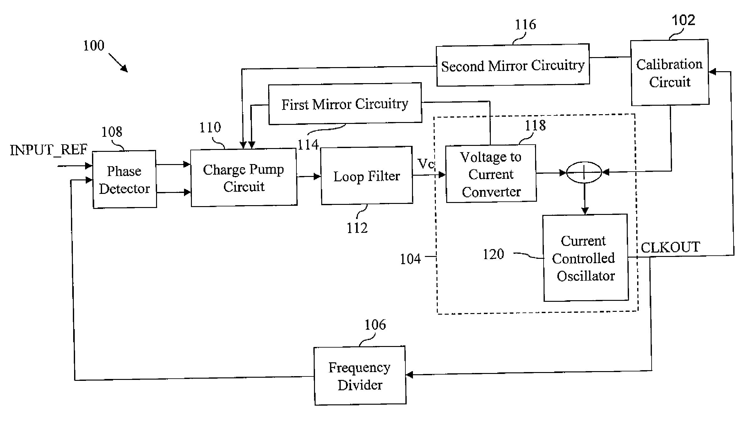
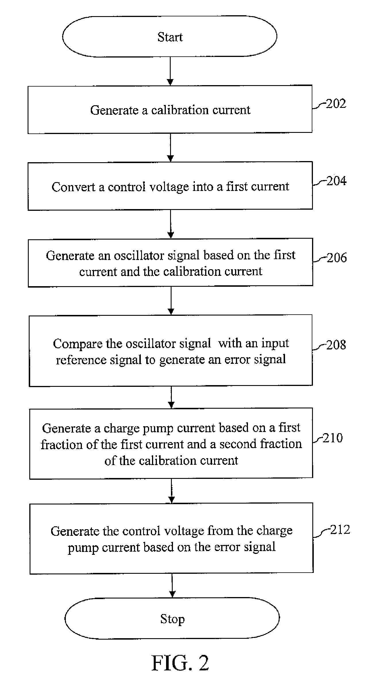
[0012]In an embodiment of the present invention, a phase-locked loop (PLL) system is provided that includes a calibration circuit for generating a calibration current. The PLL system also includes a voltage controlled oscillator (VCO), which includes a voltage-to-current converter and a current-controlled oscillator. The voltage-to-current converter converts a control voltage into a first current. The current-controlled oscillator is connected to the voltage-to-current converter and the calibration circuit, and generates an oscillator signal based on...


PUM


Abstract

A phase-locked loop (PLL) system generates an oscillator signal based on an input reference signal. A calibration circuit generates a calibration current, and a voltage-to-current converter converts a control voltage into a first current. A current-controlled oscillator generates the oscillator signal based on the first current and the calibration current. A charge pump circuit, which is connected to a phase detector, the voltage-to-current converter, and the calibration circuit, generates a charge pump current based on the first current and the calibration current. The charge pump current is used to generate the control voltage based on an error signal.

Description

BACKGROUND OF THE INVENTION[0001]The present invention relates generally to a system for generating an oscillator signal and, more specifically, to a phase-locked loop (PLL) system for generating an oscillator signal.[0002]A phase-locked loop (PLL) is a system that generates an oscillator signal having a constant phase relationship with an input reference signal. PLL systems are widely used in various applications such as radio, telecommunications, computers, and other electronic applications. A PLL system includes a voltage-controlled oscillator (VCO) for generating the oscillator signal based on a control voltage, and a phase detector for comparing the phase of the oscillator signal with that of the input reference signal and for generating an error signal based on the detected phase difference. The PLL system also includes a loop filter for filtering the error signal and generating the control voltage. Thereafter, the control voltage is provided to the VCO.[0003]Generally, PLL sy...

Claims


Application Information

Patent Timeline
IPC IPC(8): H03L7/00
CPCH03L7/0898H03L2207/06H03L7/10H03L7/099H03L7/102
Inventor THAKUR, KRISHNAJAIN, DEEPENDRA K.JAIN, VINOD
Owner NXP USA INC
Why Eureka
Try Eureka