Optical apparatus

Inactive Publication Date: 2010-10-28
PANASONIC CORP
View PDF2 Cites 2 Cited by
  • Summary
  • Abstract
  • Description
  • Claims
  • Application Information

AI Technical Summary

Benefits of technology

[0013]Therefore, a main object of the present invention is to bond optical components to a bonding surface of an optical base with a high precision and sustai

Problems solved by technology

When the residual internal stress is thus larger toward the center position in the thickness direction, the lens 5 easily loses its contact with the side surfaces 3 and 4 when the adhesive 6 is deteriorated over time or the

Method used


Image

  • Optical apparatus
  • Optical apparatus
  • Optical apparatus

Examples


embodiment 1

Preferred Embodiment 1

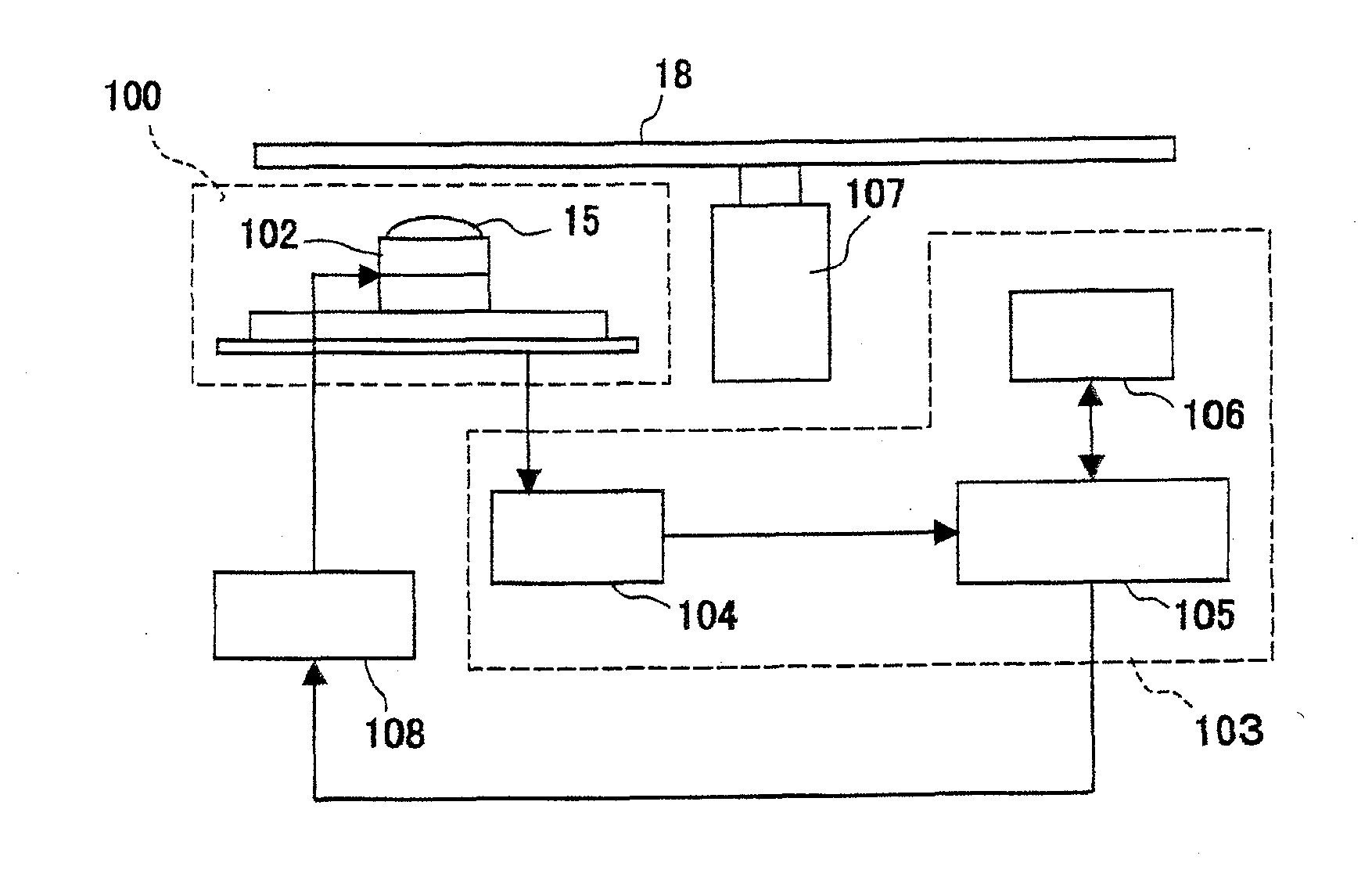
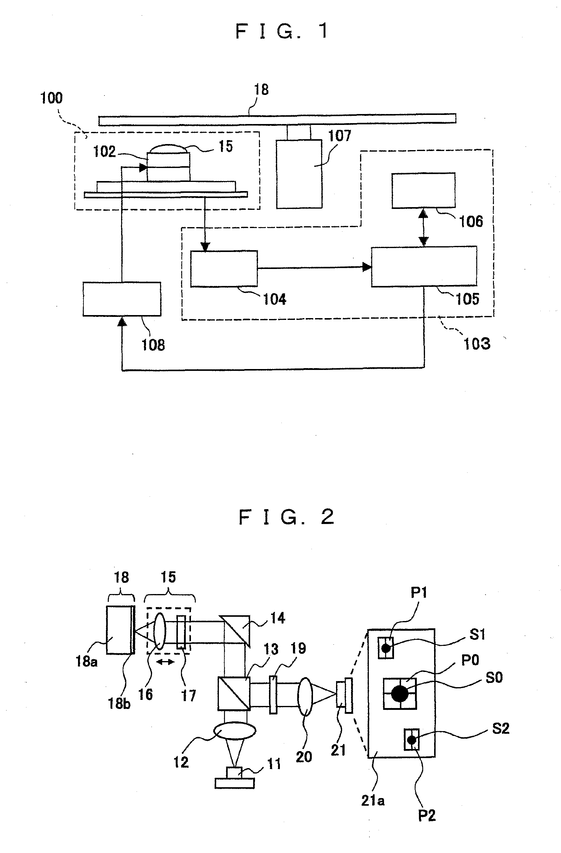
[0058]FIG. 1 is a block diagram of an optical disc drive apparatus according to a preferred embodiment 1 of the present invention. The optical disc drive apparatus has an optical pickup apparatus 100, a servo control apparatus 103, a spindle motor 107, and a servo drive circuit 108. The optical pickup apparatus 100 has an optical system including an object lens unit 15, and an actuator 102 equipped with the object lens unit 15. The servo control apparatus 103 has a focus detector circuit 104, a digital signal processor (hereinafter, referred to as DSP) 105, and a central processing unit (hereinafter, referred to as CPU) 106.

[0059]A laser beam reflected from an optical disc 18 attached to the spindle motor 107 is guided into the optical system from the object lens unit 15 of the optical pickup apparatus 100 and enters a photosensor (not shown). The photosensor converts the laser beam into an electrical signal and transmits the electrical signal to the focus dete...

embodiment 2

Preferred Embodiment 2

[0087]In the preferred embodiment 1, the lens is used as the optical component. A preferred embodiment 2 of the present invention relates to an optical apparatus wherein a prism 8 having a tetragonal shape is mounted as the optical component. FIG. 7 is a perspective view of an optical base securing portion of the prism 8 in the optical pickup apparatus according to the preferred embodiment 2. FIG. 8A is a sectional view of the optical base securing portion in view from a direction H (first direction) illustrated in FIG. 7 (corresponding to FIG. 6), and FIG. 8B is a sectional view of the optical base securing portion in view from a direction V (second direction) of FIG. 7. In the present preferred embodiment, the direction V when the prism 8 is fixed to the optical base 1 (see FIG. 7) is in parallel with an optical-axis direction of the prism 8.

[0088]A rectangular open hole 1b is formed in a recessed shape in the bonding surface 1A of the optical base 1. A width...


PUM

PropertyMeasurementUnit
Lengthaaaaaaaaaa
Luminous fluxaaaaaaaaaa
Shapeaaaaaaaaaa

Abstract

An optical apparatus according to the present invention comprises an optical base having a bonding surface, and an optical component fixedly bonded to the bonding surface with an adhesive. The optical base has an open hole formed in the bonding surface. The open hole is filled with the adhesive. The optical component contacts the open hole so that a part of the open hole is left unclosed.

Description

BACKGROUND OF THE INVENTION[0001]1. Field of The Invention[0002]The present invention relates to an optical apparatus provided in an optical pickup apparatus in which optical components, such as a lens, prism, polarizing plate and photodetector, are securely bonded to a bonding surface of an optical base with an adhesive, and a method for manufacturing the optical apparatus, and further relates to an optical pickup apparatus and an optical disc drive apparatus. The present invention more particularly relates to a technology for addressing the needs of precision improvement in assembling optical components to deal with increasingly shorter wavelengths of a semiconductor laser for achieving a higher recording density.[0003]The documents of Japanese Patent Application No. 2009-107549 filed on Apr. 27, 2009 are incorporated in its entirety, including the specification, drawings, and Scope of Claim, in the specification of the present application by reference.[0004]2. Description of The ...

Claims


Application Information

Patent Timeline
IPC IPC(8): G11B7/135G02B7/00B32B38/04
CPCG02B7/025Y10T156/1056G11B7/22G02B7/1805
Inventor YUKIMASA, TAKATOSHIYAMAZAKI, MASAHIROHATANAKA, SHINSUKE
Owner PANASONIC CORP
Why Eureka
Try Eureka