Current collecting post seal for high durability lithium-ion cells

a lithium-ion battery, current collecting post technology, applied in the direction of cell components, cell components, jackets/cases materials, etc., can solve the problems of deterioration, oxygen, water molecules or other gases or liquids not being able to be easily detected, and the interface cannot provide a long diffusion path for oxygen, water molecules or other gases or liquids

Active Publication Date: 2010-10-28
KUO HAN CHENG +1
View PDF5 Cites 11 Cited by
  • Summary
  • Abstract
  • Description
  • Claims
  • Application Information

AI Technical Summary

Benefits of technology

[0010]FIGS. 3(a)-3(d) are side views of the cover assembly of the invention showing various safety vents and electrolyte filling holes and methods of sealing same; and
[0011]FIG. 3(e) is a side view and top view of the cover assembly of the invention showing still another variation in the location of a safety vent and an electrolyte filling hole.

Problems solved by technology

Hermetic sealing is always a key issue determining service life of a Lithium-ion battery since a high voltage of the battery renders water decomposition or oxygen reduction if water or oxygen molecules are present in the electrolyte.
Such problems are often caused by improper cell sealing.
In view of the limitation of space utilized for cover construction, the metal to polymer interface at current collecting posts of the battery is usually small (only through the support of an insulation layer shaped like an O-ring) and therefore the interface can not provide a lengthy diffusion path for oxygen, water molecules or other gases or liquids penetrating through the metal to polymer interface.
The situation becomes worse once a continuous high temperature cycling condition is applied to the cells (e.g. conditions such as continuous high power operation) owing to the accelerated degradation of the polymer to metal interface.

Method used


Image

  • Current collecting post seal for high durability lithium-ion cells
  • Current collecting post seal for high durability lithium-ion cells
  • Current collecting post seal for high durability lithium-ion cells

Examples


example i

The Basic Form of the Present Invention

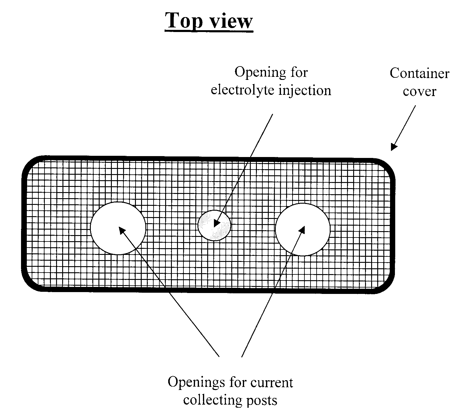
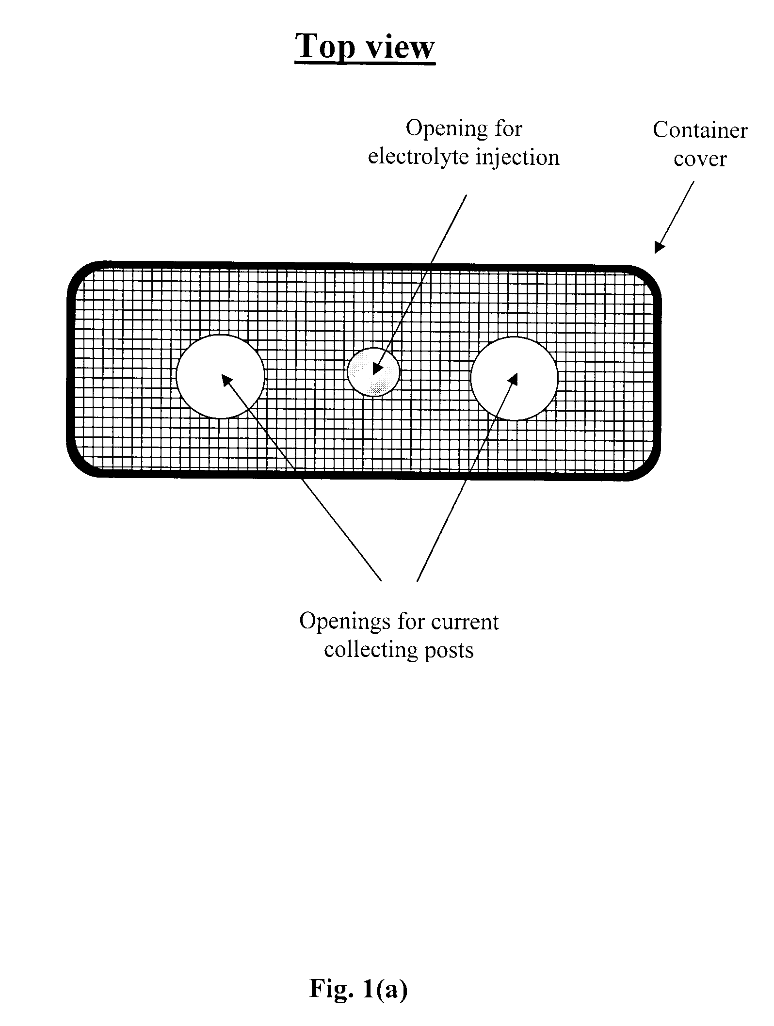
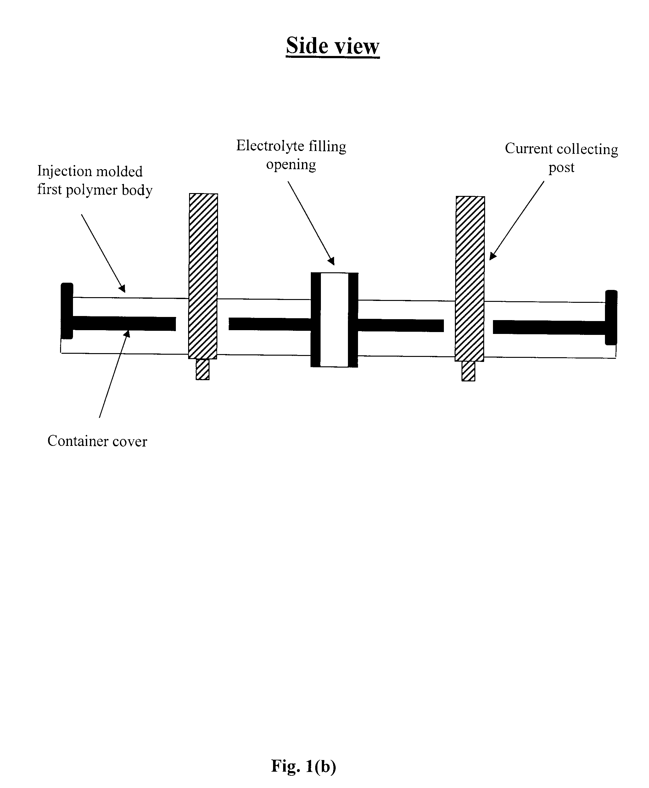
[0015]FIG. 1(a) shows a top view of a cover for a top opening of a battery container. For clarity in describing the method of the invention, step by step assembly of the cover is shown in the form of side views in FIGS. 1(b) through FIG. 1(f).

[0016]FIG. 1(b) shows the first step in fabricating the cover assembly. A first polymer body is disposed on a top and bottom surface of the container cover through an injection molding process. Current collecting posts which extend through openings in the cover are stabilized through the injection molding process as the polymer fills a gap between the cover and the current collectors.

[0017]FIG. 1(c) shows a top flange and a bottom flange disposed on the conducting posts. The flanges are forced toward each other, with the injection molded first polymer body sandwiched between. The top and bottom flanges are fused to the injection molded polymer. This step is extremely important and is preferably carried out...

example ii

An Alternative Form of Assembly of the Present Invention

[0039]Referring to FIGS. 2(a)-2(c) a current collecting post, a top flange, a bottom flange and a cover are pre-assembled via mechanical assembling or welding. The current collecting posts, top flanges, and bottom flanges are assembled relative to the cover using a mold, in the configuration shown in FIG. 2(a), and the polymer injection molding is conducted on the overall assembly. The resultant cover becomes a monolith as shown in FIG. 2(b). The top flanges are then sealed to the current collecting posts followed by filling a second polymer body on top of the injection molded first polymer body as shown in FIG. 2(c). Since high pressure is used during the injection molding process, a condition similar to forcing the top and bottom flanged together, as in the first method of fabrication described above, can be achieved via the present injection molding process. It should be noted that the sealing between the top flange and the ...

example iii

An Extended Form of the Present Invention

[0043]A cell cover may contain not only the openings for positive and negative current collecting posts but also additional openings for electrolyte filling or safety venting. One more example is given here for describing the design and method for making a cell cover that contains current collecting posts, an electrolyte filling opening, as well as a safety vent.

[0044]For clarity, the method described in Example II is utilized in the present example. FIG. 3(a) shows a cover containing a notch around the opening for electrolyte filling. The notch having a reduced metal thickness is designed to be a safety vent that breaks outward when internal cell pressure is built up undesirably. A current collecting post, a top flange and a bottom flange are pre-assembled via mechanical assembling or welding. The current collecting posts, top flanges, and bottom flanges are assembled relative to the cover using a mold, in the configuration shown in FIG. 3(a...


PUM

PropertyMeasurementUnit
diameteraaaaaaaaaa
sizeaaaaaaaaaa
distanceaaaaaaaaaa

Abstract

A cover assembly for a Lithium-ion battery container to improve the durability of the battery. A high pressure injection molded polymer is combined with flanges disposed on the current collecting posts of the battery to provide an improved seal for the battery cover, especially at the interface of the cover and the current collecting posts. The injection molded polymer is fused to the flanges, current collecting posts and container cover to result in a diffusion path of increased length for gases and/or liquids which are known to enter or escape from battery containers. Additional polymer layers can be applied to the assembly to further improve the seal.

Description

FIELD OF THE INVENTION [0001]The purpose of the present invention is to make high durability lithium ion batteries through the innovation of structure and processing methods utilized for making the Lithium-ion battery cover. The new structure and method disclosed for making the cover extends the service life of the resultant battery. The invention provides a battery for long term applications such as home energy storage applications or electric and hybrid electric vehicles applications.BACKGROUND OF THE INVENTION [0002]Hermetic sealing is always a key issue determining service life of a Lithium-ion battery since a high voltage of the battery renders water decomposition or oxygen reduction if water or oxygen molecules are present in the electrolyte. Such problems are often caused by improper cell sealing. Conventionally, lithium cells are small in size and capacity. Taking type 18650 cylindrical cells as an example, the cell size is 18 mm in diameter and 65 mm in height. The cell cap...

Claims


Application Information

Patent Timeline
Patent Type & Authority Applications(United States)
IPC IPC(8): H01M2/04B32B37/10H01M50/147H01M50/16H01M50/164H01M50/188H01M50/191H01M50/193H01M50/55H01M50/627
CPCB29C45/14639Y02T10/7011B29L2031/7146H01M2/0262H01M2/0287H01M2/043H01M2/0473H01M2/0482H01M2/0491H01M2/06H01M2/08H01M2/1229H01M2/1241H01M2/305H01M2/362H01M10/052B29C45/1671Y02E60/10H01M50/124H01M50/15H01M50/147H01M50/325H01M50/3425H01M50/193H01M50/627H01M50/55H01M50/16H01M50/191H01M50/188H01M50/164H01M50/60
Inventor KUO, HAN CHENGCHANGCHANG
Owner KUO HAN CHENG
Why Eureka
Try Eureka