Endoscope system, endoscope, and driving method

a technology of endoscope and endoscope, which is applied in the field of endoscope system, endoscope and driving method, can solve the problems of low image quality, serious space requirement for positioning such a frame or retention mechanism, and inability to achieve extreme thinning for a reduced diameter, etc., and achieves high image quality and reduces the diameter

Inactive Publication Date: 2010-10-28
FUJIFILM CORP
View PDF26 Cites 40 Cited by
  • Summary
  • Abstract
  • Description
  • Claims
  • Application Information

AI Technical Summary

Benefits of technology

[0011]In view of the foregoing problems, an object of the present invention is to provide an endoscope system, endoscope, and driving method in which an elongated tube of the endoscope can have a reduced diameter and images of high image quality can be produced.
[0040]According to the invention, the elongated tube of the endoscope can have a reduced diameter and images of high image quality can be produced, because the displacing device can compensate for poorly recording pixels by displacement of the distal tip relative to the image light.

Problems solved by technology

However, cladding of an optical fiber bundle constituting the fiber optic image guide does not contribute to the transmission of the image light.
There occurs a problem in that a pattern of mesh of a loss region due to the cladding appears locally within the image, and the image quality of the image will be low.
A space required for positioning such a frame or retention mechanism is a serious problem in view of the extreme thinning for a reduced diameter of an order from tens of microns to a number of millimeters.
Although high definition of an image can be obtained from the second embodiment of U.S. Pat. No. 4,618,884, the extreme thinning for a reduced diameter is still impossible because the CCD is disposed in front of the elongated tube in addition to the focusing lens system.

Method used


Image

  • Endoscope system, endoscope, and driving method
  • Endoscope system, endoscope, and driving method
  • Endoscope system, endoscope, and driving method

Examples


Embodiment Construction

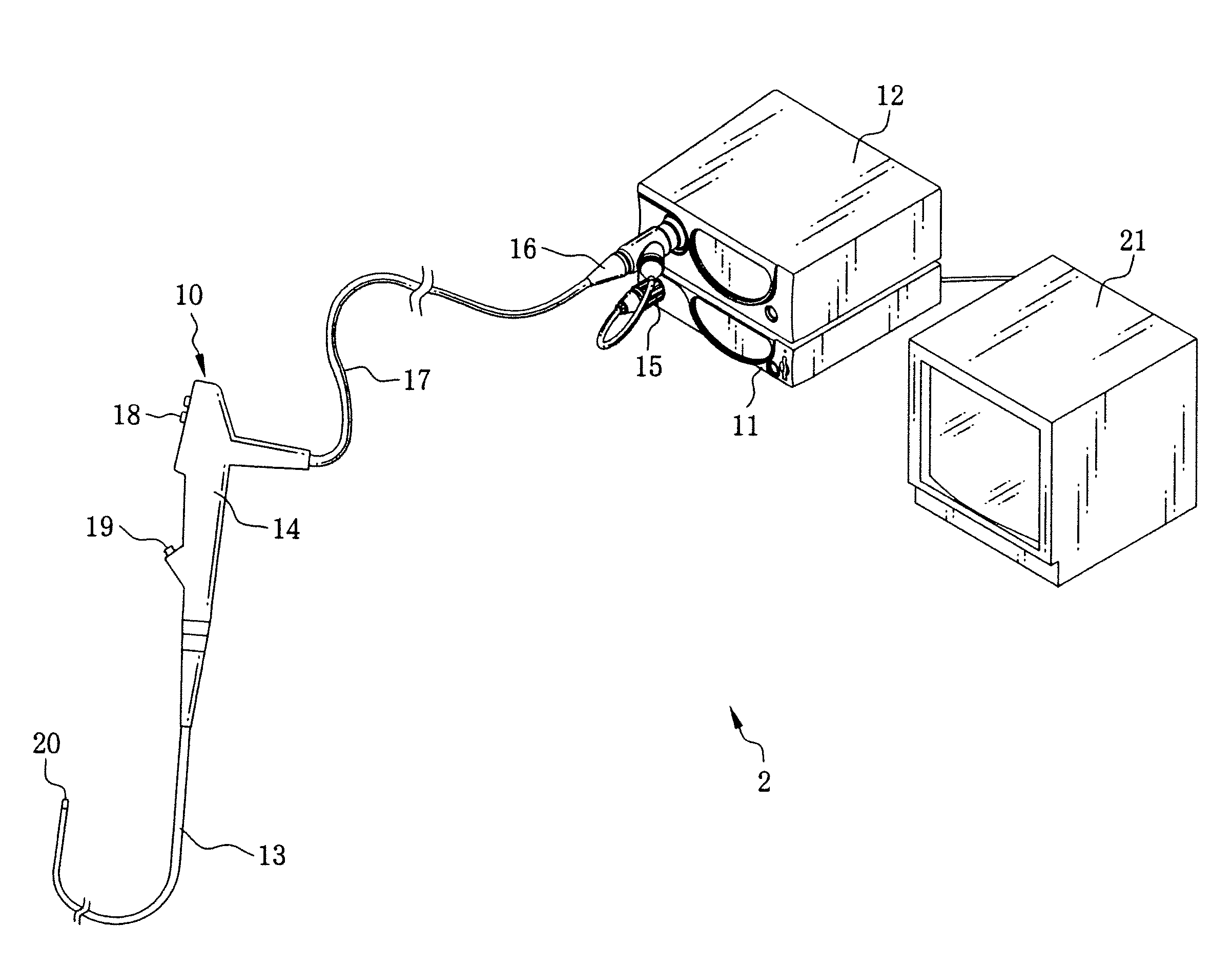
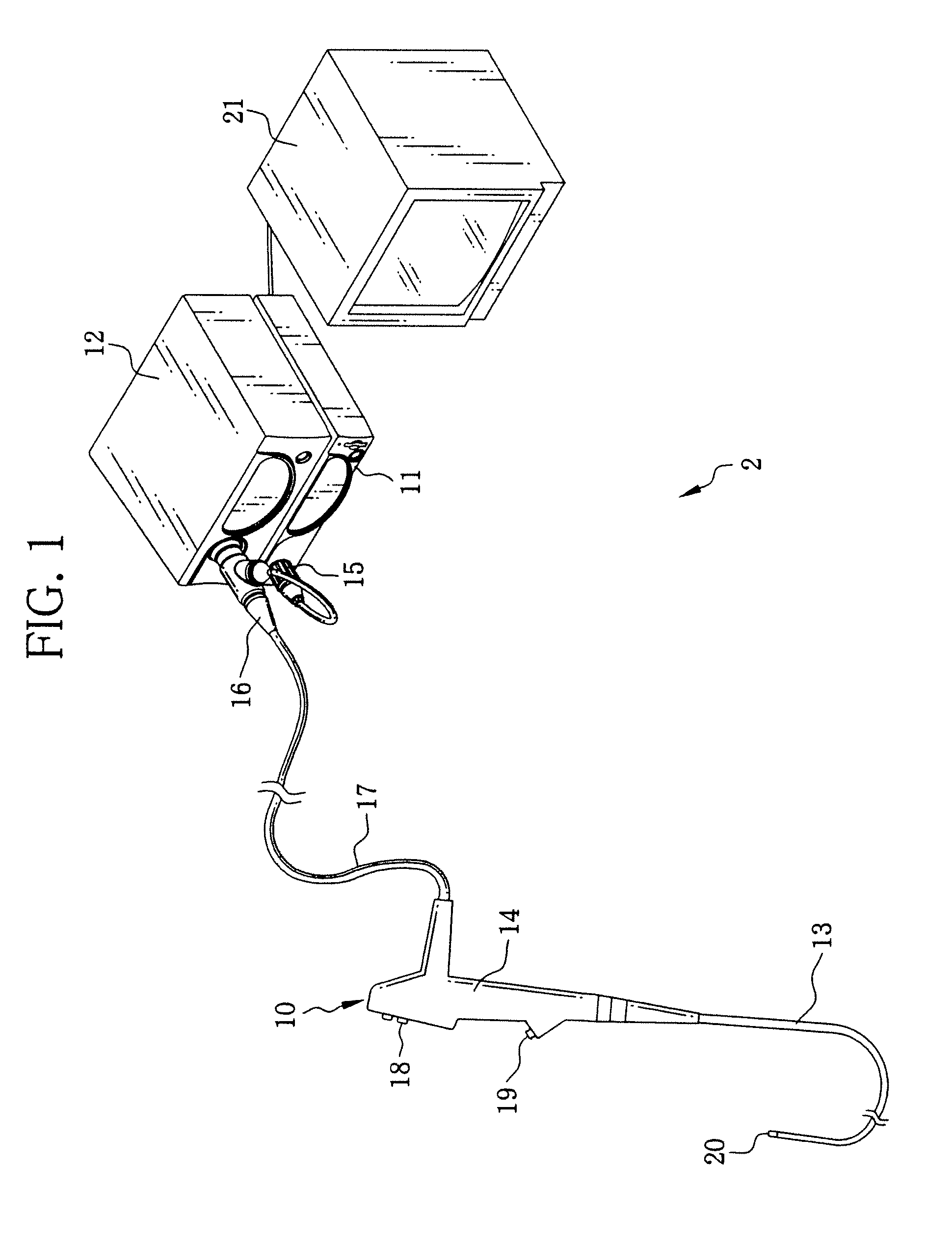
[0067]In FIG. 1, an endoscope system 2 includes an endoscope 10, a processing apparatus 11 and a light source apparatus 12. The endoscope 10 is used for imaging of various body parts in narrow lumens, for example, a pancreatic duct, bile duct, breast duct, terminal bronchioles, and the like. The endoscope 10 includes an elongated tube 13 or insertion tube, a handle 14, a first connector 15, a second connector 16 or coupler, and a universal cable 17. The elongated tube 13 is flexible and entered in a patient's body. The handle 14 is disposed at a proximal end of the elongated tube 13. The first connector 15 is plugged in the processing apparatus 11. The second connector 16 is plugged in the light source apparatus 12. The universal cable 17 extends from the handle 14 to the first connector 15 and the second connector 16.

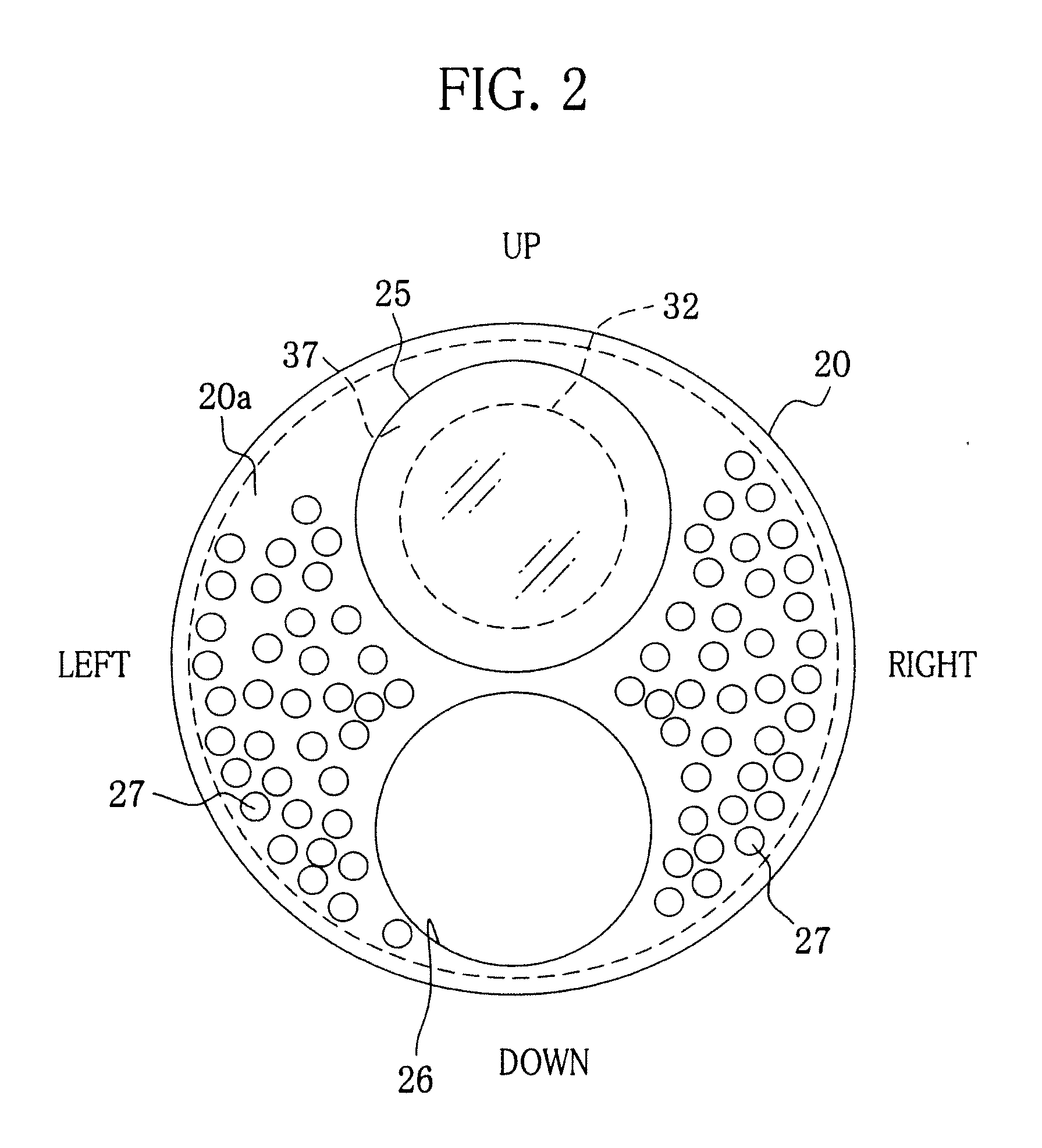
[0068]The elongated tube 13 has a thickness of 50 microns and outer diameter of 0.9 mm, and is formed from flexible material such as a Teflon (trade name), namely tetr...


PUM


Abstract

An endoscope includes an elongated tube. An objective lens system is disposed in the elongated tube, for passing image light from an object. A fiber optic image guide includes plural optical fibers bundled together, has a distal tip, is inserted through the elongated tube, for transmitting the image light focused on the distal tip by the objective lens system in a proximal direction. A displacing device displaces the distal tip laterally and periodically upon receiving entry of the image light being focused by use of a piezoelectric actuator positioned outside the distal tip. A support casing supports the distal tip inserted therein, keeps the distal tip shiftable on the displacing device, and transmits force of the piezoelectric actuator disposed outside to the fiber optic image guide.

Description

BACKGROUND OF THE INVENTION[0001]1. Field of the Invention[0002]The present invention relates to an endoscope system, endoscope, and driving method. More particularly, the present invention relates to an endoscope system, endoscope, and driving method in which an elongated tube of the endoscope can have a reduced diameter and images of high image quality can be produced.[0003]2. Description Related to the Prior Art[0004]An endoscope is an important medical instrument used in the field of the clinical medicine. Examples of the endoscope include primitive models such as a fiberscope or stomach camera, an electronic endoscope containing a CCD, and a capsule endoscope which is orally swallowed by a patient to retrieve an image.[0005]In the field of endoscopic examination, extreme thinning of a tube for a reduced diameter to produce an ultra thin tube is desired very seriously for an elongated tube of the endoscope. Various ideas for the extreme thinning for a reduced diameter have been ...

Claims


Application Information

Patent Timeline
Patent Type & Authority Applications(United States)
IPC IPC(8): A61B1/07
CPCA61B1/00096A61B1/00165A61B1/0653A61B1/04A61B1/0607A61B1/00188
Inventor OZAKI, TAKAONAKAMURA, TAKAYUKIKURODA, OSAMU
Owner FUJIFILM CORP
Why Eureka
Try Eureka