Syringe having extended blending path

a blending path and syringe technology, applied in the field of injection devices, can solve the problems of incomplete effective dissolving of solid solutes, short life times of substances, incorrect dosage, etc., and achieve the effects of maximizing flow path length, promoting effective blending, and avoiding inconvenient manufacturing

Inactive Publication Date: 2010-10-28
CHUN THOMAS
View PDF17 Cites 51 Cited by
  • Summary
  • Abstract
  • Description
  • Claims
  • Application Information

AI Technical Summary

Benefits of technology

[0012]The helical member may be inexpensively fabricated and installed into a generally conventional injection device. The helical member may be held in the compressed configuration after assembly so that it effectively serves as a solid member having a helical internal flow passage.
[0013]This construction not only promotes effective blending by maximizing flow path length, but also enables internal components of an injection device, such as a plunger, to be moved into close abutment with the flow path component, so that a high percentage of the liquid solution is successfully discharged during injection. This...

Problems solved by technology

There exist potential problems with delivery of fully blended solutions.
One potential problem is that some substances have short life times once blended with solvents, or may present problems such as precipitation from the solution over time if prepared in advance.
Another potential problem is that effective dissolving of the solid solute may possibly be incomplete.
This may result in incorrect dosage or in wasteful use of...

Method used


Image

  • Syringe having extended blending path
  • Syringe having extended blending path
  • Syringe having extended blending path

Examples


Embodiment Construction

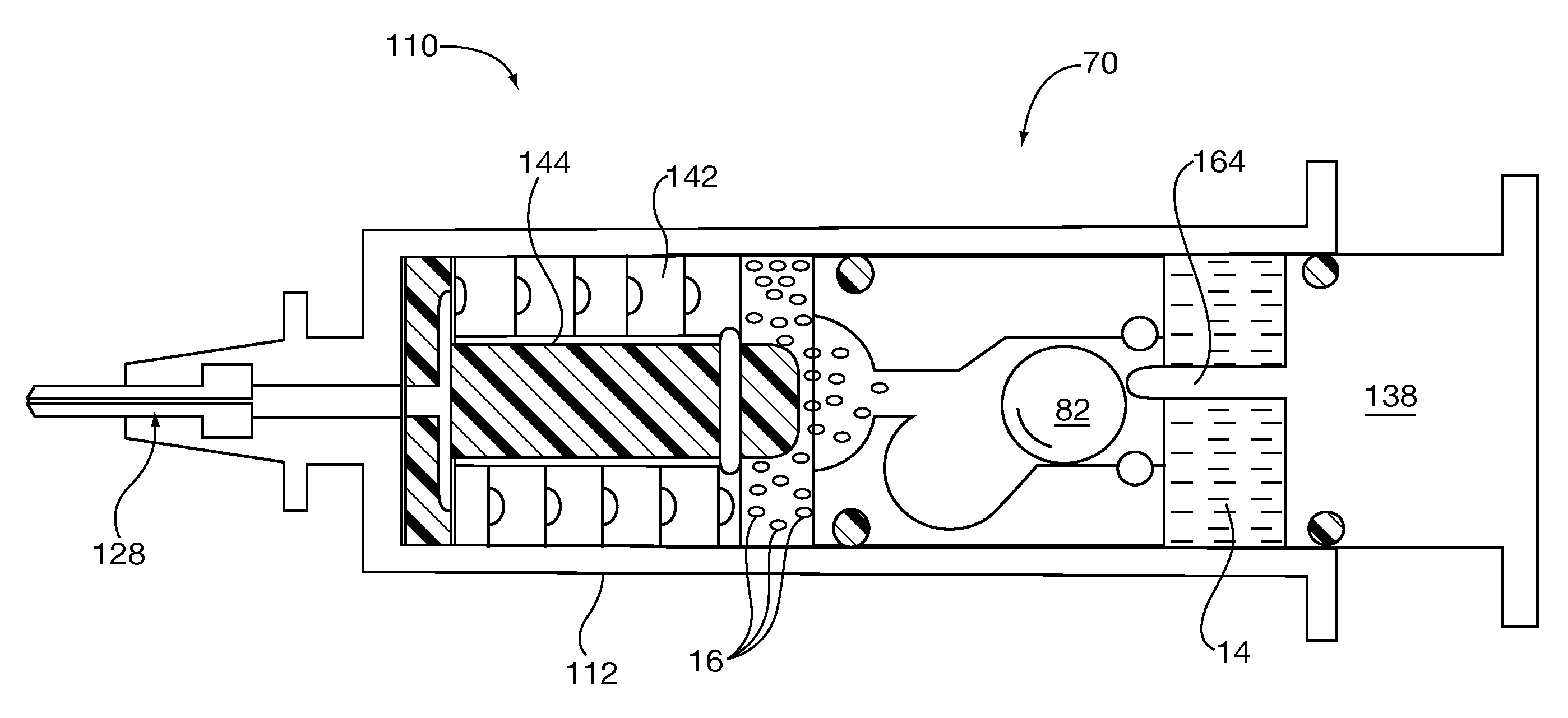
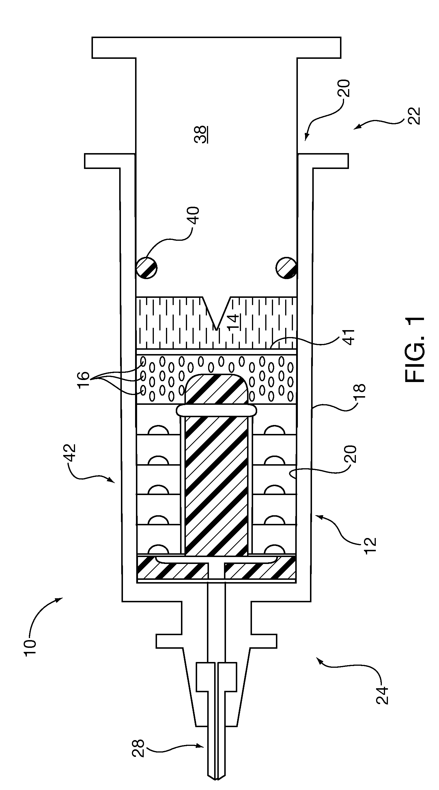
[0033]FIG. 1 of the drawings shows an injection device 10 for injecting a solution which is generated by blending of a liquid solvent 14 and a solid solute 16 which have been loaded into the injection device 10. The injection device 10 is disposed to hold the liquid solvent 14 and the solid solute 16 apart until the moment of injection, and to intermix or blend within the injection device 10 the liquid solvent 14 and the solid solute 16, thereby generating the solution which is to be injected.

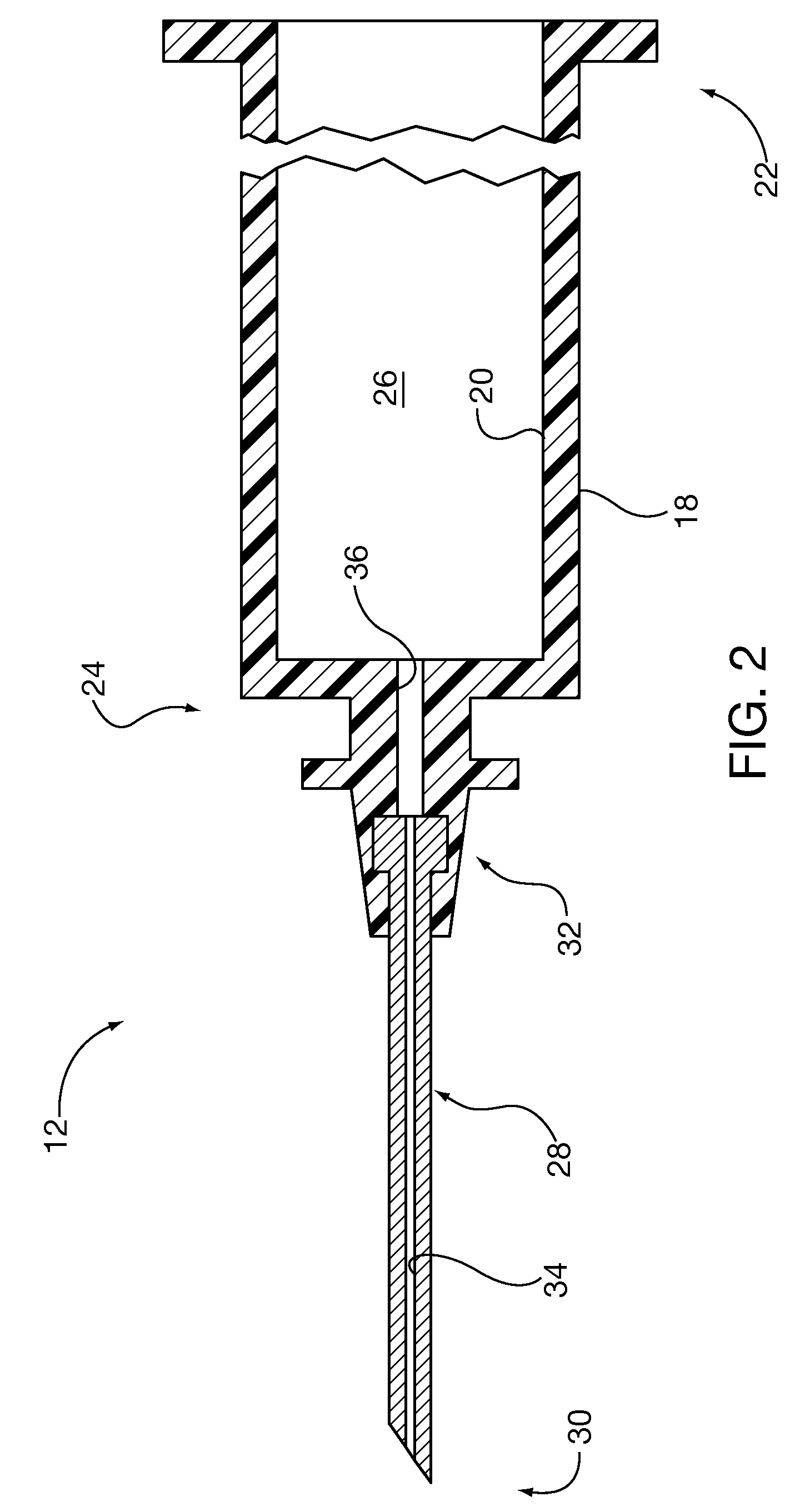
[0034]The injection device 10 may comprise a barrel 12 which is intended to contain the liquid solvent 14 and the solid solute 16. Referring also to FIG. 2, the barrel 12 may comprise a lateral wall 18 having an interior surface 20, a plunger end 22, and an opposed delivery end 24. A chamber 26 is defined within the interior surface 20 between the plunger end 22 and the delivery end 24. A hollow needle 28 may be coupled to the barrel 12 at the delivery end 24 of the barrel 12. The hollow needle...


PUM


Abstract

An injection device such as a syringe, which has a helical flow path for a solution in which the solvent and solute have been introduced. The helical flow path is formed by a helically configured member which has general overall configuration of a helical coil spring. Individual coils may be formed to have a groove located along the length of the helix. When compressed, the novel member effectively takes on a cylindrical outer configuration. Because the groove is covered and sealed by the surface of the next turn of the helix when compressed, an enclosed helical flow path is formed in the compressed member. The invention may be an injection device using the novel flow path forming member or alternatively, the flow path forming member itself.

Description

BACKGROUND OF THE INVENTION[0001]The present invention relates to injection devices such as syringes, and more particularly to an arrangement providing an extended path for effective blending of a liquid solvent and a solid solute within the injection device.SUMMARY[0002]Injection devices such as syringes are occasionally utilized to deliver liquid substances which are prepared at the last minute from solids. For example, a powdered or granular solid may be loaded into an injection device and blended with a liquid solvent within the injection device at the time of injection.[0003]There exist potential problems with delivery of fully blended solutions. One potential problem is that some substances have short life times once blended with solvents, or may present problems such as precipitation from the solution over time if prepared in advance. Another potential problem is that effective dissolving of the solid solute may possibly be incomplete. This may result in incorrect dosage or i...

Claims


Application Information

Patent Timeline
IPC IPC(8): A61M5/31
CPCA61M5/284A61M5/286A61M2005/3132A61M2005/287A61M5/31596
Inventor CHUN, THOMAS
Owner CHUN THOMAS
Why Eureka
Try Eureka