Intake control system and method for internal combustion engine

Inactive Publication Date: 2010-10-28
HONDA MOTOR CO LTD
View PDF8 Cites 11 Cited by
  • Summary
  • Abstract
  • Description
  • Claims
  • Application Information

AI Technical Summary

Benefits of technology

[0021]With the configuration of the intake control method according to the second aspect of the present invention, it is possible to obtain the same advantageous effects as provided by the first aspect of the present invention.
[0022]Preferably, the intake control method further comprises a lift-detecting step of detecting a lift of the intake valve, and the correction step comprises a limit value-setting step of setting a limit value which is at least one of an upper limit value and a lower limit value of the target intake air amount according to the detected lift of the intake valve, and a limiting step of limiting the target intake air amount based on the set limit value.
[0023]More preferably, the engine includes a variable intake cam phase mechanism for changing a cam phase of an intake cam that actuates the intake valve, with respect to a crankshaft, and the intake control method further comprises a cam phase-detecting step of detecting the cam phase, the limit value-setting step including setting the limit value further according to the detected cam phase.
[0024]More preferably, the correction step further includes an averaging step of averaging the target intake air amount by averaging calculation.
[0025]Further preferably, the intake control method further comprises a target lift-setting step of setting a target lift that serves as a target of the lift of the intake valve, and a feedback step of feedback-controlling the lift of the intake valve using a response characteristic value representative of a predetermined response characteristic, such that the lift of the intake valve becomes equal to the set target lift, and the averaging step includes setting an averaging coefficient for the averaging calculation, using the response characteristic value.
[0026]Preferably, the engine has a fixed-intake pressure operation mode in which the intake pressure is held at a fixed value by the throttle valve and the intake air amount is controlled by the lift of the intake valve, and the correction step includes correcting the target intake air amount in the fixed-intake pressure operation mode.

Problems solved by technology

In the conventional intake control system, however, when the target intake air amount is changed, there occurs an inevitable delay before the intake air amount actually becomes equal to the target intake air amount.
Since the opening of the throttle valve is corrected such that the changed intake pressure becomes equal to the target gauge pressure, it is impossible to accurately control the gauge pressure to the target gauge pressure.

Method used


Image

  • Intake control system and method for internal combustion engine
  • Intake control system and method for internal combustion engine
  • Intake control system and method for internal combustion engine

Examples


Embodiment Construction

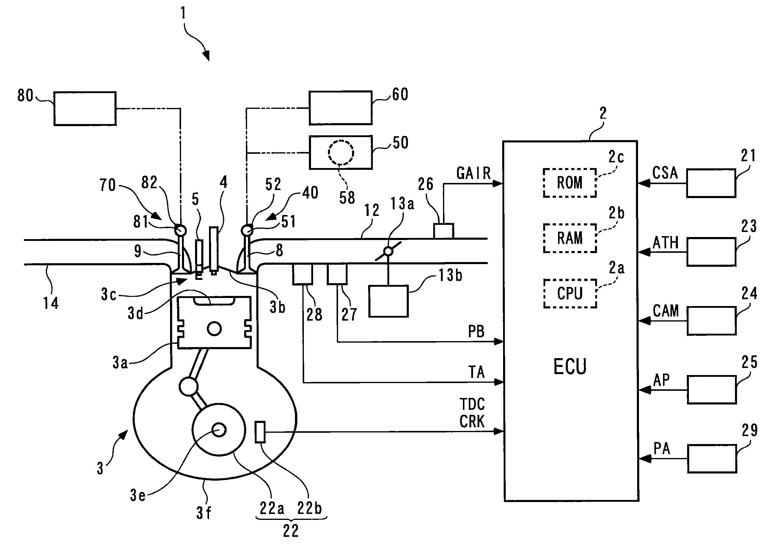
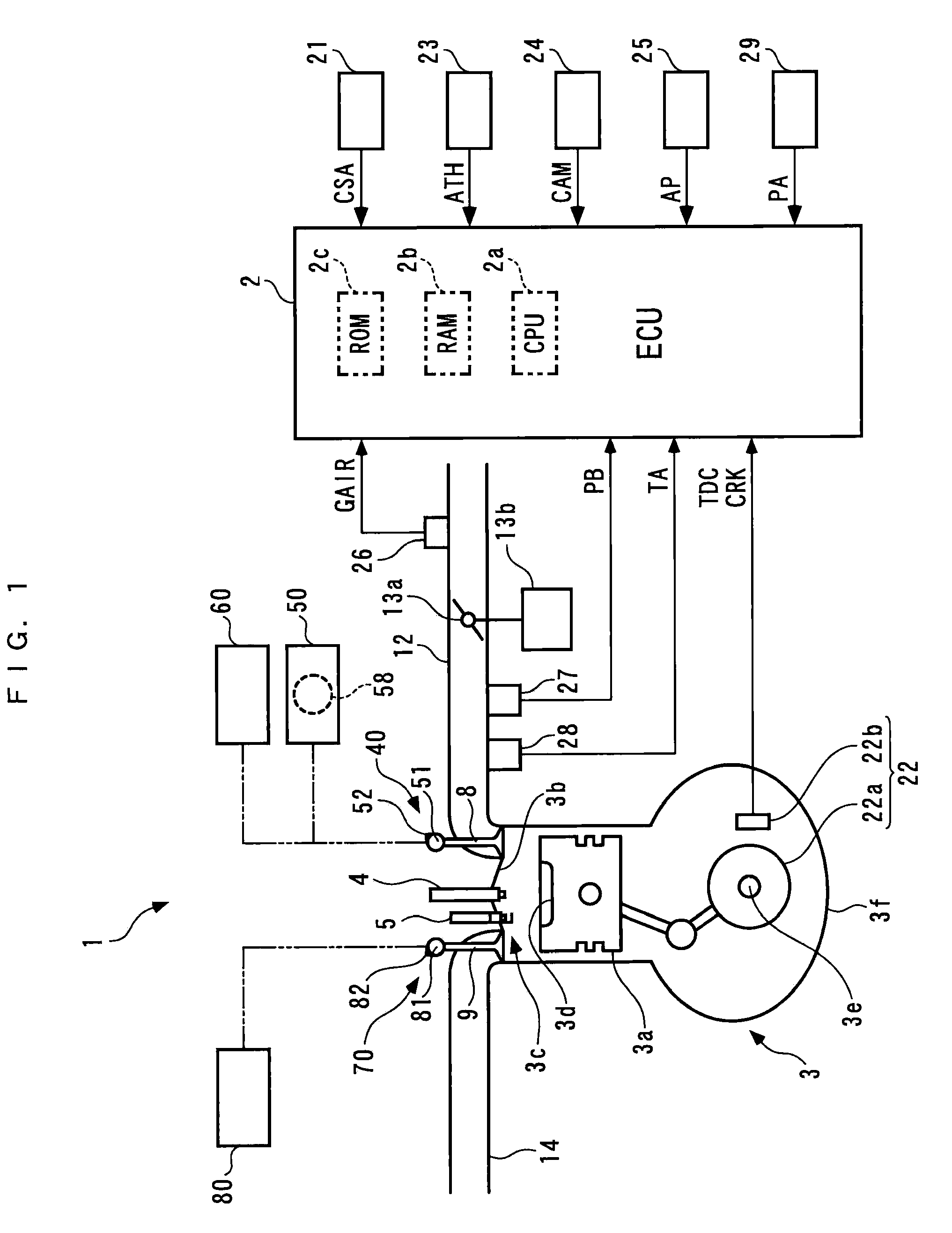
[0040]The invention will now be described in detail with reference to the drawings showing a preferred embodiment thereof. FIG. 1 is a schematic view of an intake control system 1 for an internal combustion engine according to an embodiment of the present invention, and the internal combustion engine (hereinafter referred to as “the engine”) 3 to which is applied the intake control system. As shown in FIG. 1, the intake control system 1 includes an ECU 2. As described hereinafter, the ECU 2 carries out various control processes, such as a fuel injection control process, for controlling the engine 3.

[0041]The engine 3 is a gasoline engine that has four cylinders (only one of which is shown), and is installed on a vehicle, not shown. A combustion chamber 3c is defined between a piston 3a and a cylinder head 3b for each cylinder of the engine 3. The piston 3a has a central portion of a top surface thereof formed with a recess 3d. The cylinder head 3b has a fuel injection valve (hereina...


PUM


Abstract

An intake control system for an internal combustion engine, which is capable of suppressing a change in an intake pressure caused by a change in a target intake air amount even in a transient operating condition in which the target intake air amount is varied, thereby making it possible to control the intake pressure stably and accurately. The intake control system controls an intake air amount by an intake valve lift, and controls intake negative pressure by a throttle valve. The system limits a target intake air amount based on upper and lower limit values set according to the intake valve lift and an intake cam phase, and corrects the target intake air amount by averaging the same using averaging calculation such that the change therein is delayed. A throttle valve opening is set according to the corrected target intake air amount.

Description

BACKGROUND OF THE INVENTION[0001]1. Field of the Invention[0002]The present invention relates to an intake control system and method for an internal combustion engine, for adjusting an intake air amount by changing the lift of an intake valve using a variable intake lift mechanism, and adjusting intake pressure using a throttle valve.[0003]2. Description of the Related Art[0004]Conventionally, there is known an intake control system for an internal combustion engine as disclosed e.g. in Japanese Laid-Open Patent Publication (Kokai) No. 2008-196474. The internal combustion engine is equipped with a variable intake lift mechanism for adjusting an intake air amount by continuously changing the lift of an intake valve, and a throttle valve for adjusting intake pipe pressure by changing the opening of the throttle valve. In the intake control system, a target intake air amount is calculated according to operating conditions of the engine, and based on the calculated target intake air amo...

Claims


Application Information

Patent Timeline
IPC IPC(8): F02D41/00F01L1/34
CPCF02D13/02F02D13/0226F02D41/0002Y02T10/18F02D2041/1431F02D2250/41Y02T10/42F02D2041/002Y02T10/12Y02T10/40
Inventor TAKAMIYA, HIDEHARU
Owner HONDA MOTOR CO LTD
Why Eureka
Try Eureka