Estimation of engine-out NOx for real time input to exhaust aftertreatment controller

Active Publication Date: 2010-08-24
SOUTHWEST RES INST
View PDF3 Cites 37 Cited by
  • Summary
  • Abstract
  • Description
  • Claims
  • Application Information

AI Technical Summary

Problems solved by technology

Internal combustion engines are a major contributor to harmful emissions.

Method used


Image

  • Estimation of engine-out NOx for real time input to exhaust aftertreatment controller
  • Estimation of engine-out NOx for real time input to exhaust aftertreatment controller
  • Estimation of engine-out NOx for real time input to exhaust aftertreatment controller

Examples


Embodiment Construction

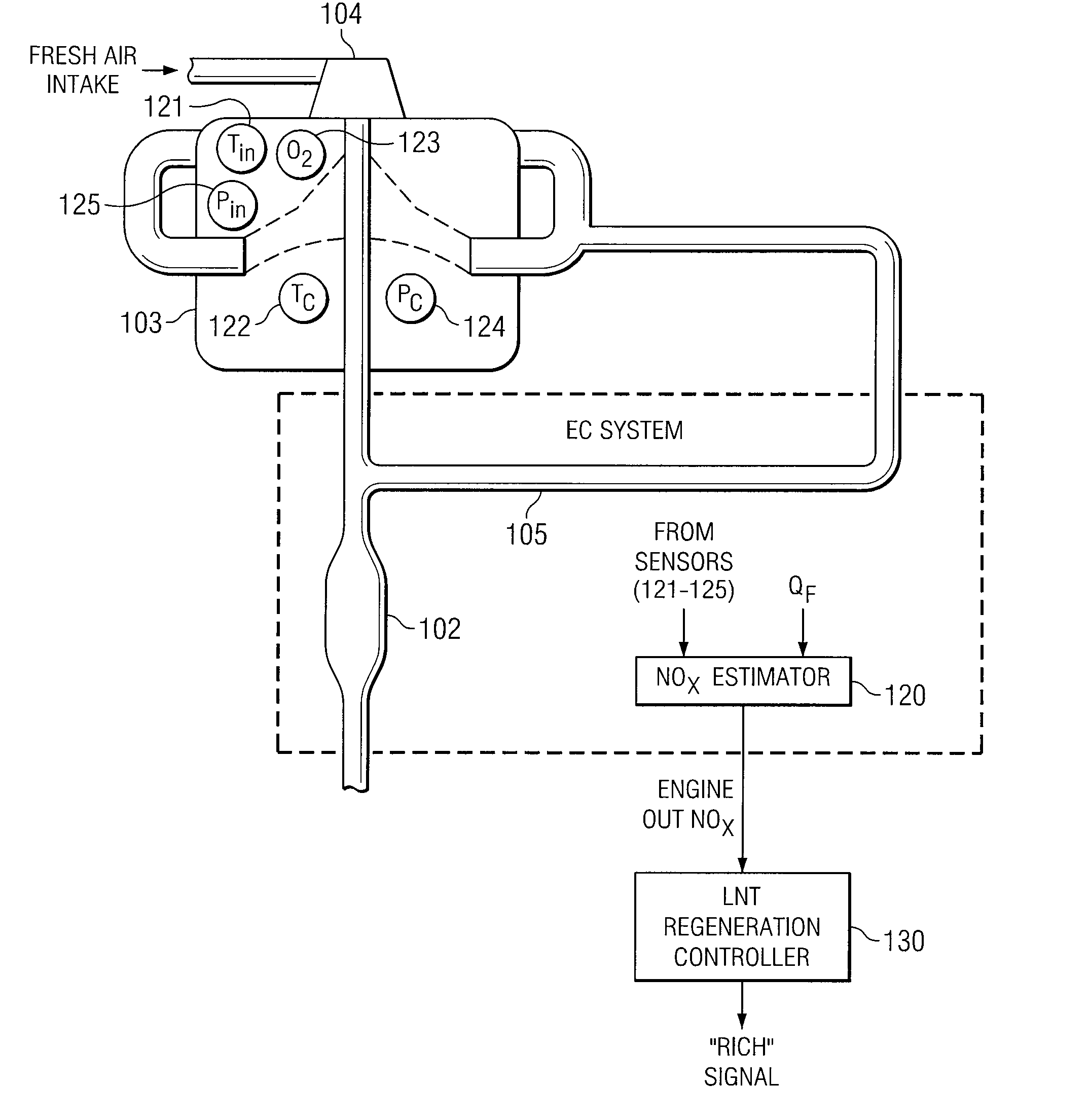
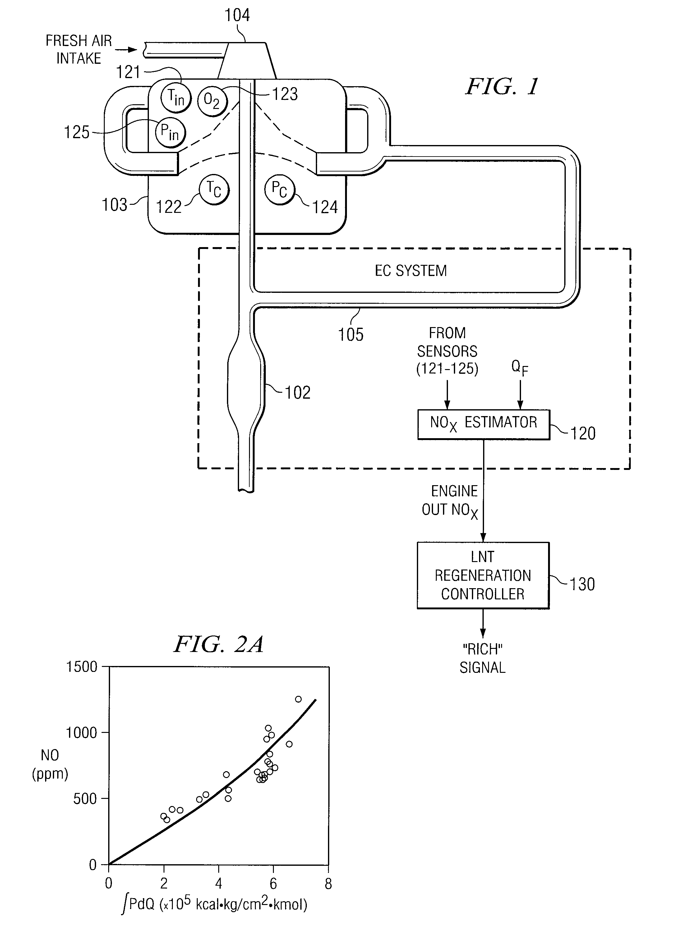
[0011]The following description is directed to a system and method, used in conjunction with an EGR-equipped diesel engine, for estimating engine-out NOx emissions. The NOx is estimated from the following parameters: 1) engine speed, 2) fuel injection quantity, 3) cylinder pressure, 4) intake O2 concentration, and 5) an “effective” temperature, based on coolant and intake manifold temperatures.

[0012]In practice, one application of the system and method is to relate the engine-out NOx to the amount of NOx accumulated in an exhaust after treatment device, such as a NOx reduction device in the exhaust line downstream of the engine. If the accumulated NOx can be estimated, it can then be determined whether the NOx reduction device needs regeneration.

[0013]FIG. 1 illustrates a diesel engine 103 having a NOx estimation unit 120 for estimating engine-out NOx. Engine 103 is also equipped with an air-charging device 104, such as a turbocharger, and an EGR (exhaust gas recirculation) loop 105...


PUM


Abstract

A method and system for estimating engine-out NOx from a diesel engine. The estimation is calculated from a mathematical model that expresses engine-out NOx as functions of cylinder pressure, intake oxygen, and effective temperature, respectively. Input data for each of these functions may be obtained from fuel quantity data and from measured data, the latter including intake pressure, cylinder pressure, intake oxygen concentration, coolant temperature, and intake manifold temperature.

Description

TECHNICAL FIELD OF THE INVENTION[0001]This invention relates to reducing exhaust emissions from internal combustion engines, and more particularly to estimating the amount of NOx emissions from a diesel engine.BACKGROUND OF THE INVENTION[0002]Internal combustion engines are a major contributor to harmful emissions. Internal combustion engines dominate land transportation propulsion—cars, trucks, off-highway vehicles, railroad, marine, motorcycles—as well as provide mechanical and electrical power for a wide range of large and small applications. The two dominant types of internal combustion engines are spark-ignition and diesel. The amount and composition of the emissions exhausted from these engines depend on the details of the processes that occur within the engine during operation, the characteristics of the fuel used, and the type of emissions control system used.[0003]For diesel engines, the main pollutants of concern are nitrogen oxides (NOx) and particulate matter (PM). The l...

Claims


Application Information

Patent Timeline
Patent Type & Authority Patents(United States)
IPC IPC(8): G01M15/10
CPCF02D41/1462G01M15/102F02D41/0047
Inventor SASAKI, SHIZUOSARLASHKAR, JAYANT V.NEELY, GARY D.
Owner SOUTHWEST RES INST
Why Eureka
Try Eureka