Quasi Free Piston Engine

a free-flowing, piston engine technology, applied in the direction of positive displacement liquid engines, piston pumps, machines/engines, etc., can solve the problems of inability to stop the combustion piston at the correct position at tdc during the compression stroke, the effect of insufficient control can go beyond unacceptable performance and be destructive to the engine, and the difficulty of stopping the combustion piston at the correct position at tdc remains

Inactive Publication Date: 2010-11-04
UNITED STATE OF AMERICA AS REPRESENTED BY THE ADMINISTATOR OF THE U S ENVIRONMENTAL PROTECTION AGENCY THE
View PDF15 Cites 36 Cited by
  • Summary
  • Abstract
  • Description
  • Claims
  • Application Information

AI Technical Summary

Benefits of technology

[0026]Accordingly, it is one object of the present invention to provide an efficient means for ensuring exact stoppage o

Problems solved by technology

Therefore one major challenge is how to control the exact stopping point of the piston assembly as it approaches the top dead center (TDC) position of the combustion piston during its compression stroke, (and more problematic, the exhaust stroke for a four-stroke configuration) in a way that is accurate and repeatable (for millions of events).
A similar challenge is associated with the control of the exact stopping point of the assembly as it approaches the bottom dead center (BDC) position of the combustion piston during the expansion or power stroke.
This is especially so since the friction of each stroke can vary (especially during warm-up or transient operation), the quantity of fuel provided for each combustion event can vary, the beginning of the combustion process can vary, the rate of combustion and its completeness can vary, the pressure of the hydraulic fluid being supplied to the pump can vary, the pressure of the hydraulic fluid being expelled can vary, and many other operating parameters that influence each stroke can vary; therefore, the accurate control of the TDC and BDC positions is very challenging.
The consequences of inadequate control can go beyond unacceptable performance and be destructive to the engine, such as if the combustion piston hits the cylinder head of the combustion chamber or the pumping piston contacts the end of the pumping chamber.
Because of the challenges posed by operational control, most true free piston engines of the prior art operate on a two stroke cycl

Method used


Image

  • Quasi Free Piston Engine
  • Quasi Free Piston Engine
  • Quasi Free Piston Engine

Examples


Embodiment Construction

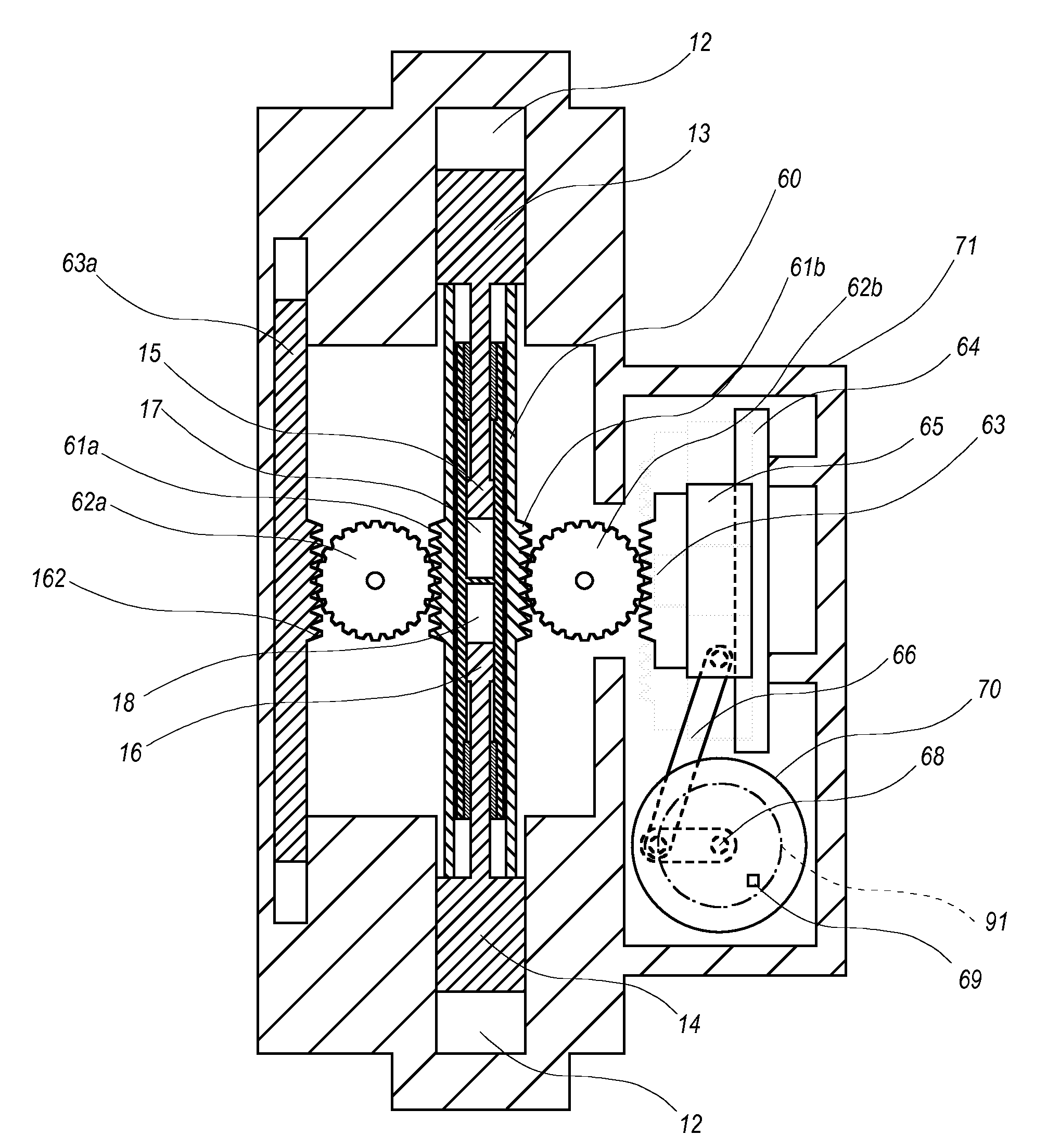
[0040]A cross-sectional view of a preferred embodiment of a two-stroke quasi free piston engine of the present invention is presented in FIG. 6. The quasi free piston engine of FIG. 6 operates similarly to the free piston engine of FIG. 4. Opposed combustion pistons 13 and 14 slide within cylinders 12 that reside in block 71. Combustion pistons 13 and 14 respectively have axially and inwardly attached pumping pistons 15 and 16 which slide within pumping cylinders 17 and 18. Pumping cylinders 17 and 18 are directly analogous to the same numbered components of FIG. 2; their respective fluid connections, not as easily shown in FIG. 5, will be best understood with reference to FIG. 2. Pumping cylinders 17 and 18 respectively communicate with hydraulic lines 22 and 23 which contain valves 24a and 24b, which further connect with passage 25 through valve 32, which passage is further connected to the low pressure hydraulic fluid source (hydraulic lines, valves, and fluid source not shown in...


PUM


Abstract

A quasi free piston engine uses, a small, lightweight crankshaft to connect the piston assemblies of the free piston engine with a flywheel. While most of the power output from the combustion pistons is extracted by pumping pistons as hydraulic power, the small crankshaft and flywheel ensure exact TDC position of the combustion pistons in operation, and provide a rotating means to drive combustion cylinder intake and exhaust valves. Flywheel speed may be monitored to provide feedback on power extraction for further control of the system. In addition, a hydraulic push-rod system for efficient valve actuation is provided.

Description

FIELD OF INVENTION[0001]The present invention relates to the conversion of chemical energy (fuel) into hydraulic, electric, or pneumatic energy, particularly by means of free-piston internal combustion engines. The general field of application is the efficient production of hydraulic, electric or pneumatic power for mobile and non-mobile power needs.BACKGROUND OF THE INVENTION[0002]1. Free Piston Engines in General[0003]Hydraulic power is frequently produced by rotating the drive shaft of a hydraulic pump by means of a rotational power source such as an electric motor or an internal combustion engine. The most efficient such pumps utilize a reciprocating-piston design in which the rotational power delivered to the drive shaft is converted to a linear motion of a set of pumping pistons that pump fluid and thereby create hydraulic power. When a conventional internal combustion engine is employed to drive the pump, the rotational drive power it delivers to the pump must also be convert...

Claims


Application Information

Patent Timeline
IPC IPC(8): F02B71/00
CPCF01B7/16F01B9/047F02B75/32F01B11/08F02B71/045F01B11/004
Inventor GRAY, JR., CHARLES L.
Owner UNITED STATE OF AMERICA AS REPRESENTED BY THE ADMINISTATOR OF THE U S ENVIRONMENTAL PROTECTION AGENCY THE
Why Eureka
Try Eureka