Feedwater debris trap

a technology of debris traps and steam generators, which is applied in the direction of steam/vapor condensers, steam boiler components, corrosion prevention, etc., can solve the problems of affecting the operation of the steam generator

Active Publication Date: 2010-11-04
BABCOCK & WILCOX CANADA LIMITED
View PDF8 Cites 9 Cited by
  • Summary
  • Abstract
  • Description
  • Claims
  • Application Information

AI Technical Summary

Benefits of technology

[0005]The present invention is drawn to a vapor generator having a pressure vessel and a plurality of heat exchanger tubes extending within the vessel to accommodate the flow therethrough of a hot primary fluid. An economizer is disposed within the vessel in spaced-apart relation thereto to define an annular downcomer passage and a lower portion of the tube bundle enclosed by the downcomer. The economizer portion of the heat exchange surface of the tubes preheats feedwater fluid by heat transfer from the tubes. A debris filter trap is provided for capturing and retaining debris carried by the feedwater fluid to prevent entry of the debris into the economizer.

Problems solved by technology

Debris from the feedwater system, transported by the feedwater flow, can become lodged between the tubes of the tube bundle and cause wearing and / or denting of the tubes.
; none of these prior art patents provide a debris trap within the steam generator pressure vessel to capture and prevent debris carried by the feedwater from entering the economizer tube section.

Method used


Image

  • Feedwater debris trap
  • Feedwater debris trap
  • Feedwater debris trap

Examples


Embodiment Construction

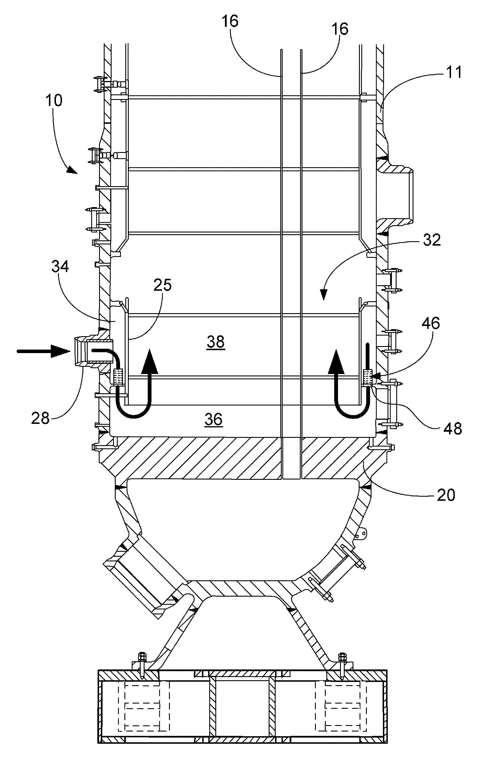
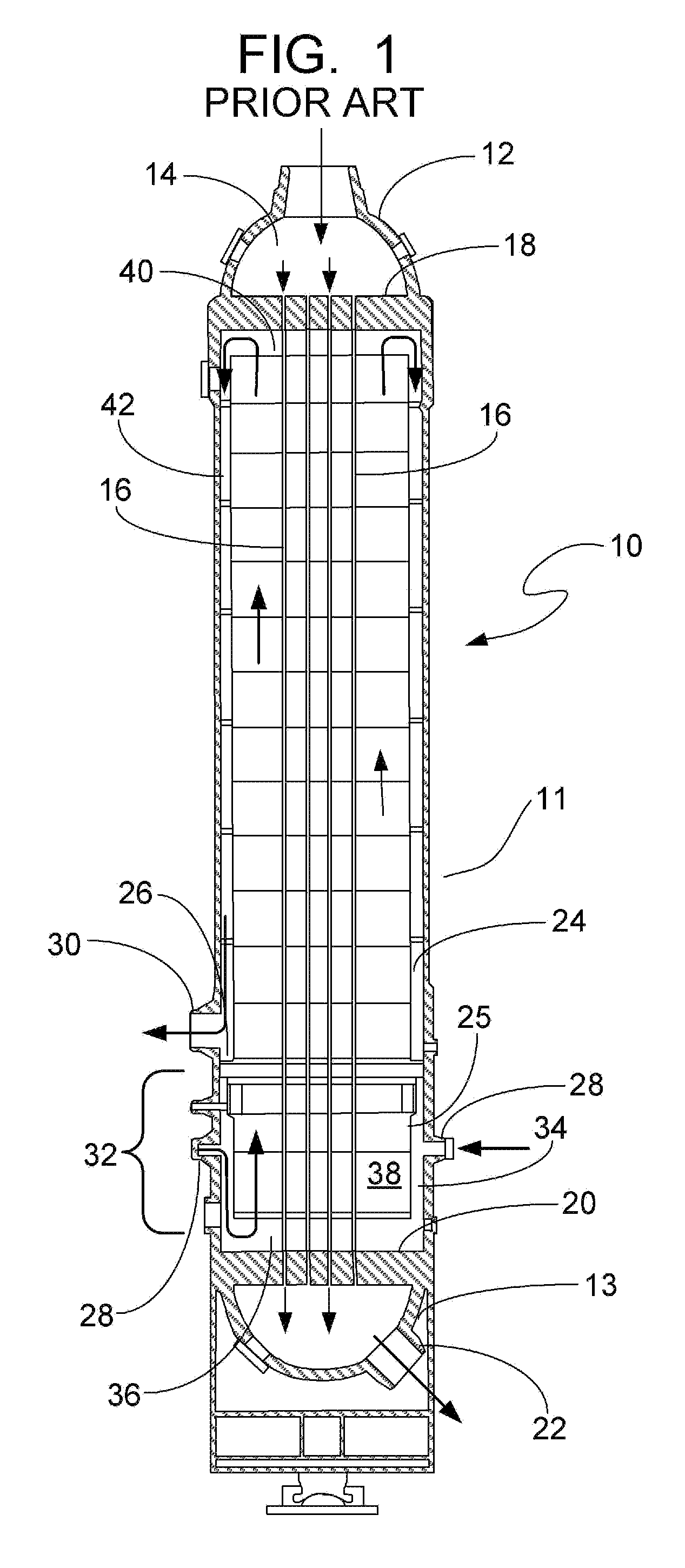
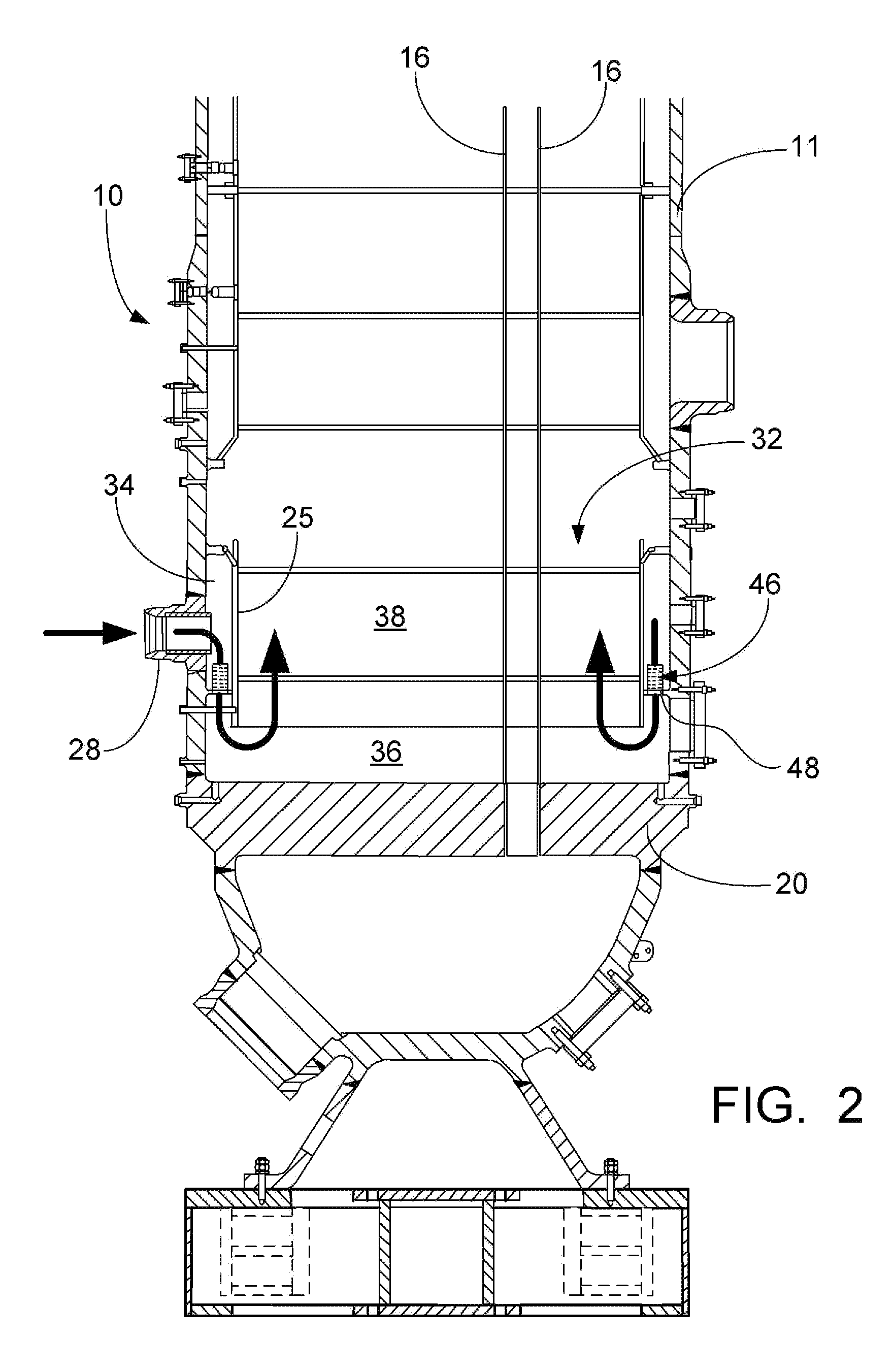
[0014]FIG. 1 depicts a prior art once-through steam generator 10 comprising a vertically elongated, generally cylindrical pressure vessel or shell 11 closed at its opposite ends by an upper head 12 and a lower head 13. A hot primary fluid such as the coolant from a nuclear reactor (not shown) is passed through the pressure vessel 11, and therein undergoes indirect heat exchange with a secondary fluid, such as water, fed into the pressure vessel 11. The primary fluid enters a plenum chamber 14 at the upper head 12 of the pressure vessel 11 and passes through tubes 16, received in upper and lower tubesheets 18 and 20, whence it exits through the coolant outlet nozzle 22 for recirculation to the reactor.

[0015]Within the pressure vessel 11 there is an upper shroud 24 and a lower shroud 25, both are open ended and surround the bundle of tubes 16. An annular ring plate 26, connected at its inner edge to the upper shroud 24 and at its outer edge to the inner wall of pressure vessel 11, ser...


PUM

PropertyMeasurementUnit
diameteraaaaaaaaaa
diameteraaaaaaaaaa
lengthaaaaaaaaaa

Abstract

A debris filter trap to prevent potentially damaging debris carried by the feedwater entering the pressure vessel of a once through steam generator from entering into the section of tubes which are positioned within the confines of an integrally contained economizer of the once through steam generator. The trap will remove foreign material, from the feedwater flow, that is larger than the space between the tubes, and thus prevent debris particles that are large enough to get lodged in the tube spacing from entering the economizer.

Description

FIELD AND BACKGROUND OF INVENTION[0001]The present invention relates generally to once through steam generators for nuclear power plants, and in particular to a trap for preventing feedwater debris from entering the space between the section of tubes positioned in the economizer which is integrally contained in the steam generator pressure vessel.[0002]The pressurized steam generators, or heat exchangers, associated with nuclear power stations transfer the reactor-produced heat from the primary coolant to the secondary coolant, which in turn drives the plant turbines. Many of these steam generator pressure vessels have integral economizers wherein subcooled feedwater is directly channeled into the lower section of the tube bundle. The pressure vessels may about 75 feet long and have an outside diameter of about 12 feet. Within one of these steam generator pressure vessels, straight tubes, through which the primary coolant flows, may be typically ⅝ inch in outside diameter, but have ...

Claims


Application Information

Patent Timeline
Patent Type & Authority Applications(United States)
IPC IPC(8): F28F19/00
CPCF22B29/06F22B37/18B01D29/33F22D1/00F22B1/026F22B37/002B01D29/52Y02E30/30B01D24/00G21C15/00G21C15/02
Inventor KLARNER, RICHARD G.
Owner BABCOCK & WILCOX CANADA LIMITED
Why Eureka
Try Eureka