Method for the permanent connection of two components by means of glass or metal solder

a technology of metal soldering and component, applied in the direction of welding/cutting media/materials, manufacturing tools, soldering media, etc., can solve the problems of high transient mechanical internal tension, high thermal expansion coefficient of metal layer and material to which the components are to be joined, and insufficient wetness of known solder materials on the surface of electrically nonconductive materials in particular, and achieve thermal conductivity of the layer system providing adhesion. , the effect of improving the adhesive ability

Inactive Publication Date: 2010-11-04
FRAUNHOFER GESELLSCHAFT ZUR FOERDERUNG DER ANGEWANDTEN FORSCHUNG EV
View PDF34 Cites 23 Cited by
  • Summary
  • Abstract
  • Description
  • Claims
  • Application Information

AI Technical Summary

Benefits of technology

[0014]The invention is a method for the permanent connection of two components, of which at least one component comprises an electrically nonconductive material, preferably a glass-like material, by soldering using a glass or metal solder as a solder material. A layer system providing adhesion is applied to at least one of the two components, to which the solder material is applied, which is brought indirectly or directly into contact with the other component and heated to a soldering temperature characteristic for the solder material. A permanent soldered connection results between both components after cooling so that measures are to be taken in order to entirely or at least largely avoid the mechanical internal tensions occurring in previously known soldered connections, in order to provide a permanent and loadable join connection between the components. In addition to the aspect of improving the adhesive capability between the solder connection implemented by heating and the surfaces of the particular components to be joined to one another, the thermal conductivity of the layer system providing adhesion is also to be improved for the purposes of melting the solder material applied to the at least one layer system which forms as rapidly and homogeneously as possible upon thermal heat introduction.

Problems solved by technology

However, it has been shown that the known solder materials only inadequately wet the surfaces of electrically nonconductive materials in particular and also many metal materials.
If adhesive layers which comprise metal are used, as is entirely the case in the above-mentioned cited art, the disadvantage is that the thermal expansion coefficients of the metal layer and the material to which the components are to be joined typically differ strongly.
These factors may result in the formation of high transient mechanical internal tensions within the layer composite or the substrate surface upon heating of the soldering composite, such as tensile or compressive stress, which already result in cracking in the layer or in the substrate material or the detachment of the particular adhesive layer from the substrate surface during soldering in the worst case.
Strongly pronounced mechanical internal tensions may also occur in the interface between the solder material and the applied layer system upon cooling of the solder, which may result in layer failure.
It is obvious that the strength of the solder composite is reduced by internal tensions inherent to the layer and in the worst case can already result in failure of the solder composite upon the action of slight mechanical strains.
A further disadvantage of adhesive layers comprising metals is that as a consequence of the comparatively high reflection values for IR radiation, the metal layers represent a heat barrier.
It becomes more difficult to introduce the heat required for melting the solder material efficiently into the solder material, and / or higher heating powers are required, which may result in higher thermal strains of the participating components and / or longer processing times.

Method used


Image

  • Method for the permanent connection of two components by means of glass or metal solder
  • Method for the permanent connection of two components by means of glass or metal solder
  • Method for the permanent connection of two components by means of glass or metal solder

Examples


Embodiment Construction

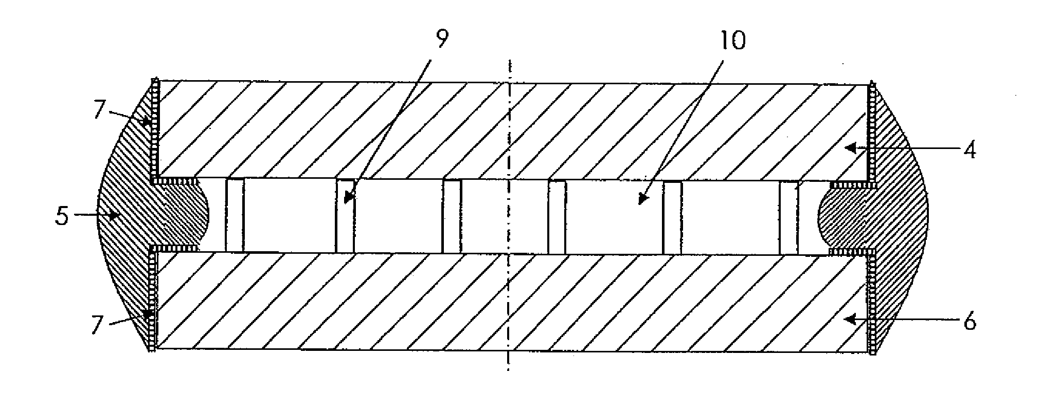
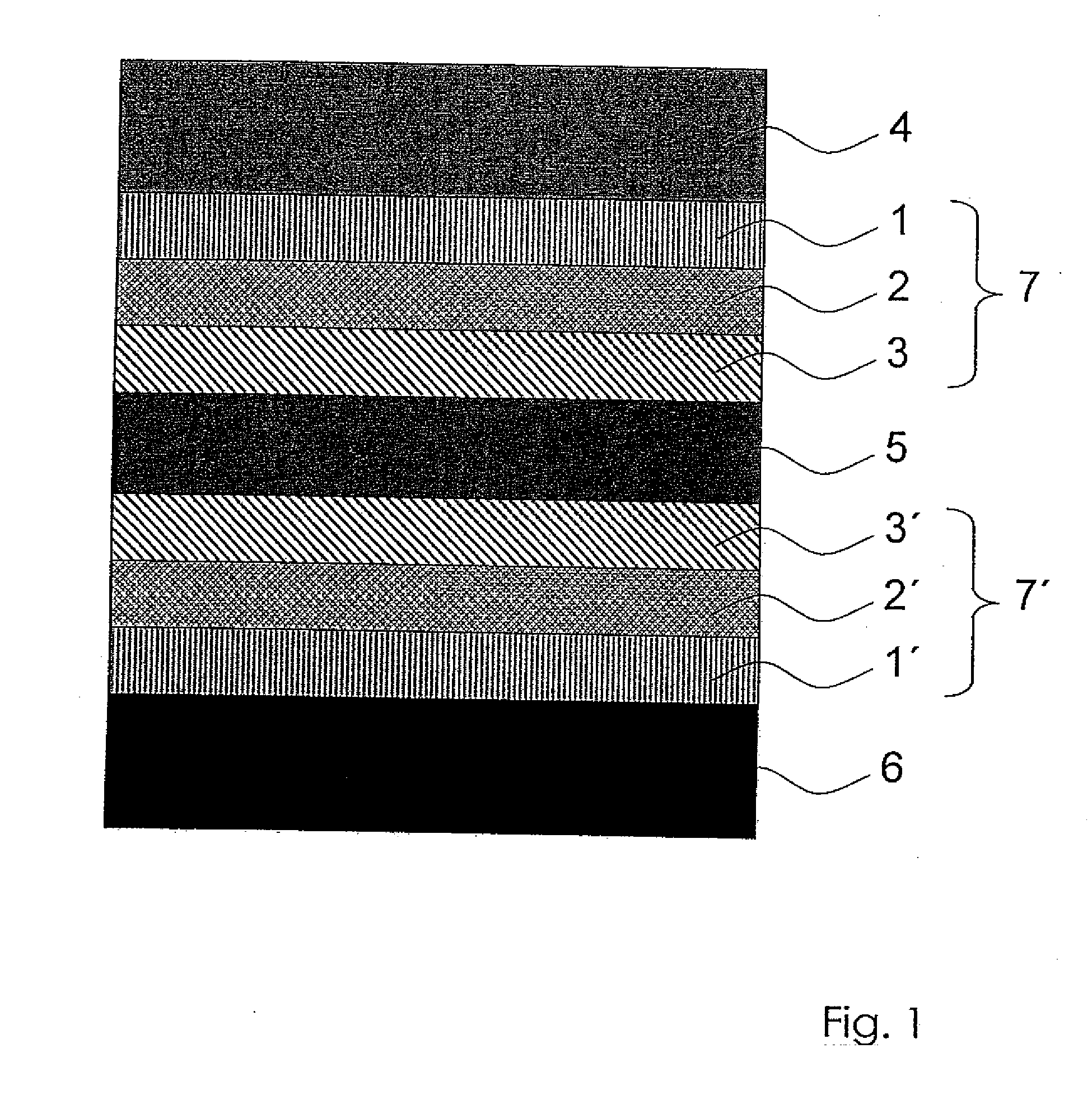
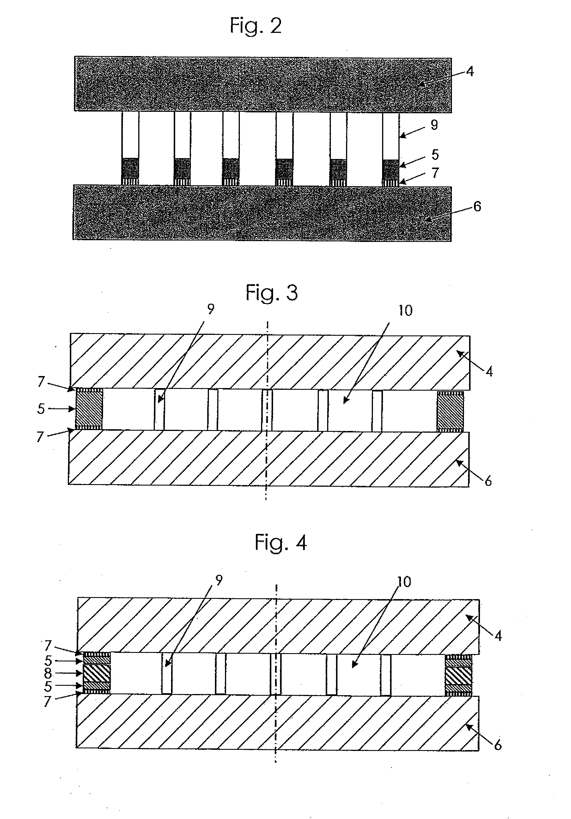
[0031]FIG. 1 shows the layer sequence of a soldered connection for the permanent connection of two components 4, 6, of which at least one component comprises an electrically nonconductive material, preferably a glass-like material, such as quartz glass or a ceramic. The soldered connection described hereafter is thus suitable for producing a permanent connection between a glass component and a metal component and between two glass components or similar electrically nonconductive components. Layer systems 7, 7′, each comprising three layers, which are composed of an adhesive layer 1, 1′, a solderable layer 2, 2′, and an oxidation protective layer 3, 3′ if a metal solder is used, are located on the surfaces of the components 4, 6 to be connected to one another. The adhesive layers 1, 1′, which comprise oxidic, carbidic, and / or nitridic components or mixed compounds thereof, are each selected in regard to their material selection so that they have the best possible wetting and / or adhes...


PUM

PropertyMeasurementUnit
thicknessaaaaaaaaaa
temperaturesaaaaaaaaaa
electrically nonconductiveaaaaaaaaaa

Abstract

The invention is a method for permanent connection of two components by soldering employing a glass or metal solder as the solder material. A layer system providing adhesion is applied to both components, between which the solder material is introduced. the layer system is heated to a soldering temperature characteristic for the solder material and results in a permanent solder connection between both components after cooling. The layer system providing adhesion has an adhesive layer applicable directly to the component and a solderable layer. The adhesive layer, if a glass solder is used, contains oxidic, carbidic, or nitridic components or mixed compounds thereof and, if a metal solder is used, the adhesive layer contains carbidic or nitridic components or mixed compounds thereof.

Description

BACKGROUND OF THE INVENTION[0001]1. Field of the Invention[0002]The invention relates to a method for the permanent connection of two components, of which at least one component comprises an electrically nonconductive material, by soldering employing a glass or metal solder as the solder material, in which a layer system providing adhesion is applied to at least one of the two components, onto which the solder material is applied, which is brought indirectly or directly into contact with the other components and is heated to a soldering temperature characteristic for the solder material and results in a permanent soldered connection between both components after cooling.[0003]2. Description of the Prior Art[0004]For manifold applications, for example, in the field of optics or measuring technology, permanent connections must be produced between components made of different or similar materials, such as glass to glass or glass to metal, on which various demands are made. For example,...

Claims


Application Information

Patent Timeline
Patent Type & Authority Applications(United States)
IPC IPC(8): B23K31/02
CPCB23K1/19B23K35/001B23K35/004B23K35/0238B23K35/025B23K35/262C03C27/08B23K35/3033C03C17/36C03C27/044C03C27/046C03C27/06B23K35/3006
Inventor HAGEN, JANFABER, THORSTENKUBLER, RALNERKLEER, GUNTER
Owner FRAUNHOFER GESELLSCHAFT ZUR FOERDERUNG DER ANGEWANDTEN FORSCHUNG EV
Why Eureka
Try Eureka