Low power electric operated thermostatic mixing valve

a thermostatic mixing valve, low-power technology, applied in the direction of valve operating means/release devices, process and machine control, etc., can solve the problems of slow response time of wax filled elements, affecting the stability of the valve, and affecting the operation of the valve, etc., to achieve the effect of low power consumption and fast settling

Active Publication Date: 2010-11-04
RIVLIN EITAN
View PDF6 Cites 14 Cited by
  • Summary
  • Abstract
  • Description
  • Claims
  • Application Information

AI Technical Summary

Benefits of technology

[0013]It is therefore, an object of the present invention to provide a frictionless, pressure balanced proportioning valve assembly and drive unit, targeted for fast settling, low power consuming, electric operated thermostatic mixing valves.

Problems solved by technology

However, such directly driven thermostatic valves fail to provide a constant outlet water temperature, if the pressure or the temperature of the water in one of the supply lines, rises or drops, the temperature of the outlet water is temporarily changed.
Consequently, a typical error of up to 2° C. from the initial setting, can be expected in wax element thermostatic valves, in the event of pressure or temperature fluctuations in one of the supply lines.
Furthermore the response time of such wax filled elements is slow, typical temperature restore times after pressure fluctuation events are in the range of 1.5 seconds or above, such a delay may cause inconvenience to the user, as well as oscillations or hunting mostly apparent at low flow rates.
a. Most of the disclosed inventions are using conventional proportioning valves fitted with an electric drive unit. These devices require significant force to overcome pressure imbalances, friction of a fluid-to-air seal and friction of internal proportioning valve fluid-to-fluid seals. This in turn requires large motors having high power consumption and high mechanical inertia, further requiring computing of dedicated acceleration and deceleration algorithms, large power supply, and in-wall installation extending to AC mains power.
b. Additionally, the conventional proportioning valves generally have large volume mixing chamber resulting in a delayed reading of the mixed water temperature by the temperature sensor, such delay makes it very difficult to effectively control the proportioning valve in different flow rates, since the time required for the hot and cold water to flow from the proportioning valve seats to the temperature sensor is considerably greater at low flow rates than during high flow rates, resulting in a too wide dispersion of the feedback system time constant. Some of the cited prior art are using two independent proportioning valves, having long pathways to the mixing chamber, and even longer time delay as described above.
However such solution requires additional sensors as well as computation resources requiring more power and space.

Method used


Image

  • Low power electric operated thermostatic mixing valve
  • Low power electric operated thermostatic mixing valve
  • Low power electric operated thermostatic mixing valve

Examples


second embodiment

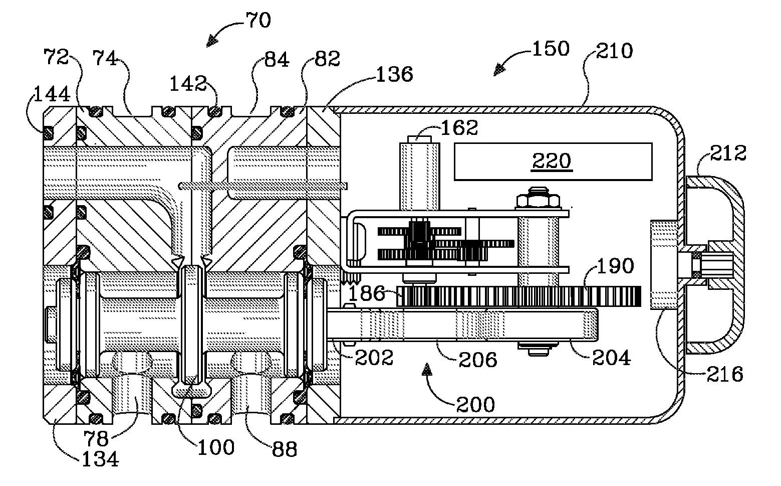
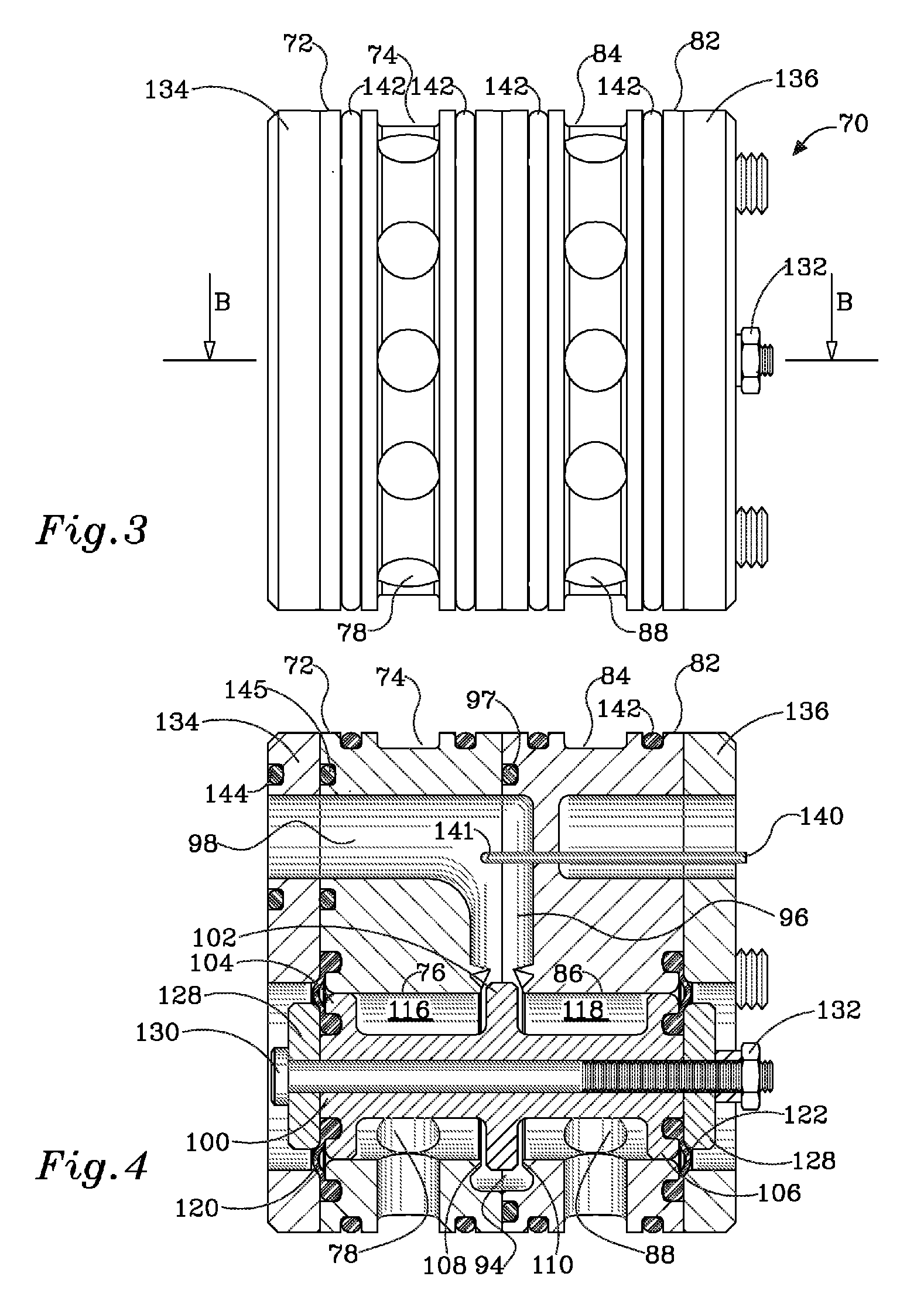
[0055]The operation of the frictionless pressure balanced proportioning valve assembly will be explained in more detail with reference to FIGS. 3 to 7, related to the present invention. Referring to the figures, there is shown a cartridge type, frictionless, pressure balanced proportioning valve assembly, generally referenced 70, composed of: first cylindrical enclosure 72, having an outer circumferential recess 74 water inlet, being in flow communication with first axial non-centric bore 76 (FIGS. 4, 5), by plurality of radial passages 78; second cylindrical enclosure 82, having an outer circumferential recess 84 water inlet, being in flow communication with second axial non-centric bore 86 (FIGS. 4, 7), by a plurality of radial passages 88.

[0056]The first and second cylindrical enclosures 72,82, are facially mated with each other, aligned such that the first axial non-centric bore 76, and second axial non-centric bore 86, are joining to a spool bore. The first and second cylindric...

first embodiment

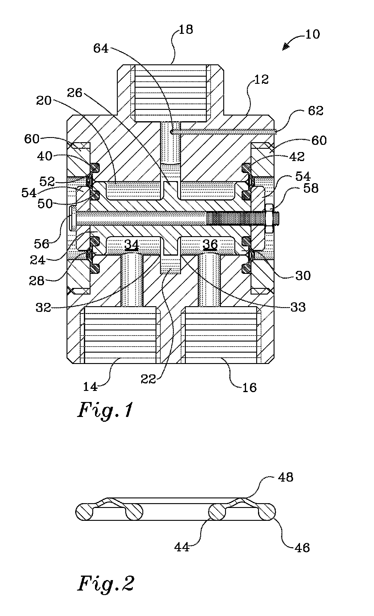
[0059]Principally, same elastic diaphragm seals 120,122, as described with reference to the present invention are disposed at both ends of the spool 100, and cylindrical enclosures 72, 82. The diaphragm seals 120, 122 are configured, by equalization, of their effective area to the lip valve seats 108, 110 actual area, for pressure balancing of first inlet tubular chamber 116 between first diaphragm seal 120 and disk 102; and pressure balancing of second inlet tubular chamber 118 between second diaphragm seal 122 and disk 102. The diaphragm seals 120, 122, constructed with inner ring 44, outer ring 46 and preferably rolling thin active portion 48 (FIG. 2), are secured in grooves 124, 126, (FIG. 5), on the outer faces of spool 100, and of cylindrical enclosures 72, 82, respectively. The diaphragm seals 120, 122 are tightened to the spool 100 by washers 128, center bolt 130 and nut 132. The seals 120,122, are tightened to the first and second cylindrical enclosures 72, 82, by fastened,...

third embodiment

[0073]As disclosed above, and already demonstrated in the preceding paragraphs, it is an object of the present invention to provide the frictionless proportioning valve assembly and the drive means, as a compact replaceable cartridge. In order that such cartridge may fit into the traditional single handed mixing faucets housings, and possibly adopt the common ceramic disk mechanism for simultaneous volume control of both inlets, the present invention, is disclosed and explained in detail with reference to FIGS. 15 to 17.

[0074]Referring to the figures, there is shown a frictionless, pressure balanced proportioning valve assembly, generally referenced 250, basically similar to the assembly 70 of the second preferred embodiment, yet, instead of the outer circumferential recesses 74, 84 (FIGS. 3, 4), serving as inlets of the second embodiment , here, the first and second inlets 254, 256, respectively (FIG. 15), are facially located on the first end disk 258 with same outlet 260 there be...


PUM


Abstract

A frictionless, pressure balanced proportioning valve assembly, for low power electric operated thermostatic cartridge, composed of a housing with spaced apart hot and cold water inlets and intermediate mixed water outlet, flow communicated to a spool bore with a central widened portion; a spool, guided in the spool bore, by widened end portions, is carrying a central widened disk portion, separating the spool bore into two tubular inlet chambers; two diaphragm seals disposed at both ends of the spool and housing, pressure balancing the inlet chambers; a temperature sensor, exposed to the mixed water outlet pathway, generates a signal, readable by a control circuit; a drive unit energized by a low power electric motor, driving past gear train and eccentric shaft, a bendable connecting rod, axially displacing the spool. Axial displacement of the balanced friction-free spool, proportions flow from the hot and cold water inlets to the mixed water outlet.

Description

FIELD OF THE INVENTION[0001]The present invention relates to thermostatic mixing valves and, more specifically, to frictionless pressure balanced proportioning valve and drive system, targeted for fast settling, low power consuming, electric operated thermostatic mixing valves.BACKGROUND OF THE INVENTION[0002]Thermostatic mixing valves are known and their use is greatly spreading in developed countries mainly due to regulations enforcing, at least one central thermostatic mixing valve, in new installations. However, cost reduction, as well as recognition of the convenience and safety involved, contributes to increasing market share of thermostatic mixing valves in point of use installations such as individual basins, bathtubs and showers, as well.[0003]Presently, most thermostatic mixing valves utilize a thermally responsive wax element directly coupled to a spring loaded proportioning valve. However, such directly driven thermostatic valves fail to provide a constant outlet water t...

Claims


Application Information

Patent Timeline
Patent Type & Authority Applications(United States)
IPC IPC(8): G05D23/13G05D23/19
CPCF01P2007/146G05D23/1393F16K31/047
Inventor RIVLIN, EITAN
Owner RIVLIN EITAN
Why Eureka
Try Eureka