Hydraulic assembly for a hydraulic vehicle brake system with traction control

Active Publication Date: 2010-11-04
ROBERT BOSCH GMBH
View PDF3 Cites 25 Cited by
  • Summary
  • Abstract
  • Description
  • Claims
  • Application Information

AI Technical Summary

Problems solved by technology

It is disadvantageous that with a single pressure sensor, exact conclusions about the pressure conditions of all the hydraulic portions of the vehicle brake system cannot be

Method used


Image

  • Hydraulic assembly for a hydraulic vehicle brake system with traction control
  • Hydraulic assembly for a hydraulic vehicle brake system with traction control

Examples


Embodiment Construction

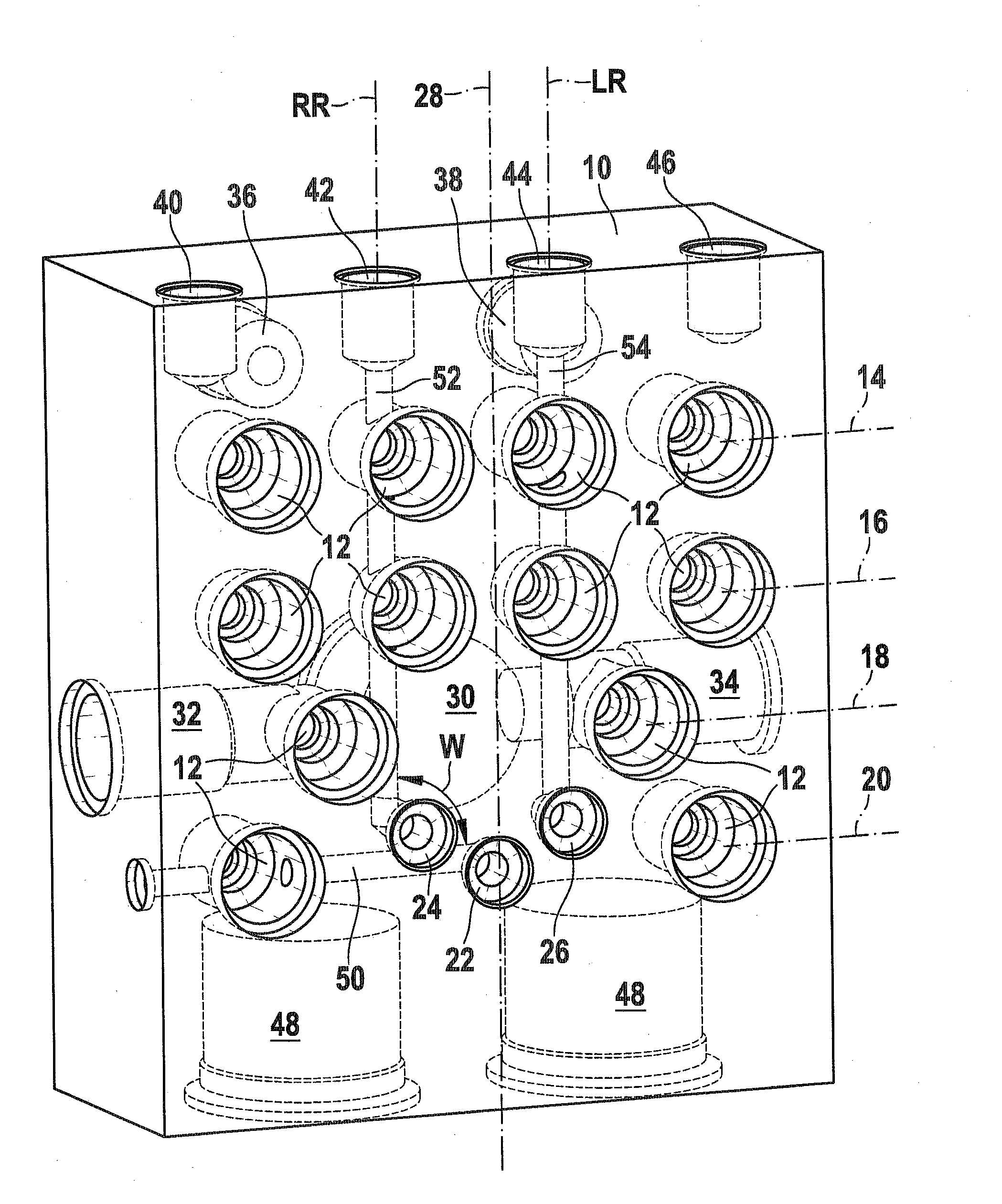
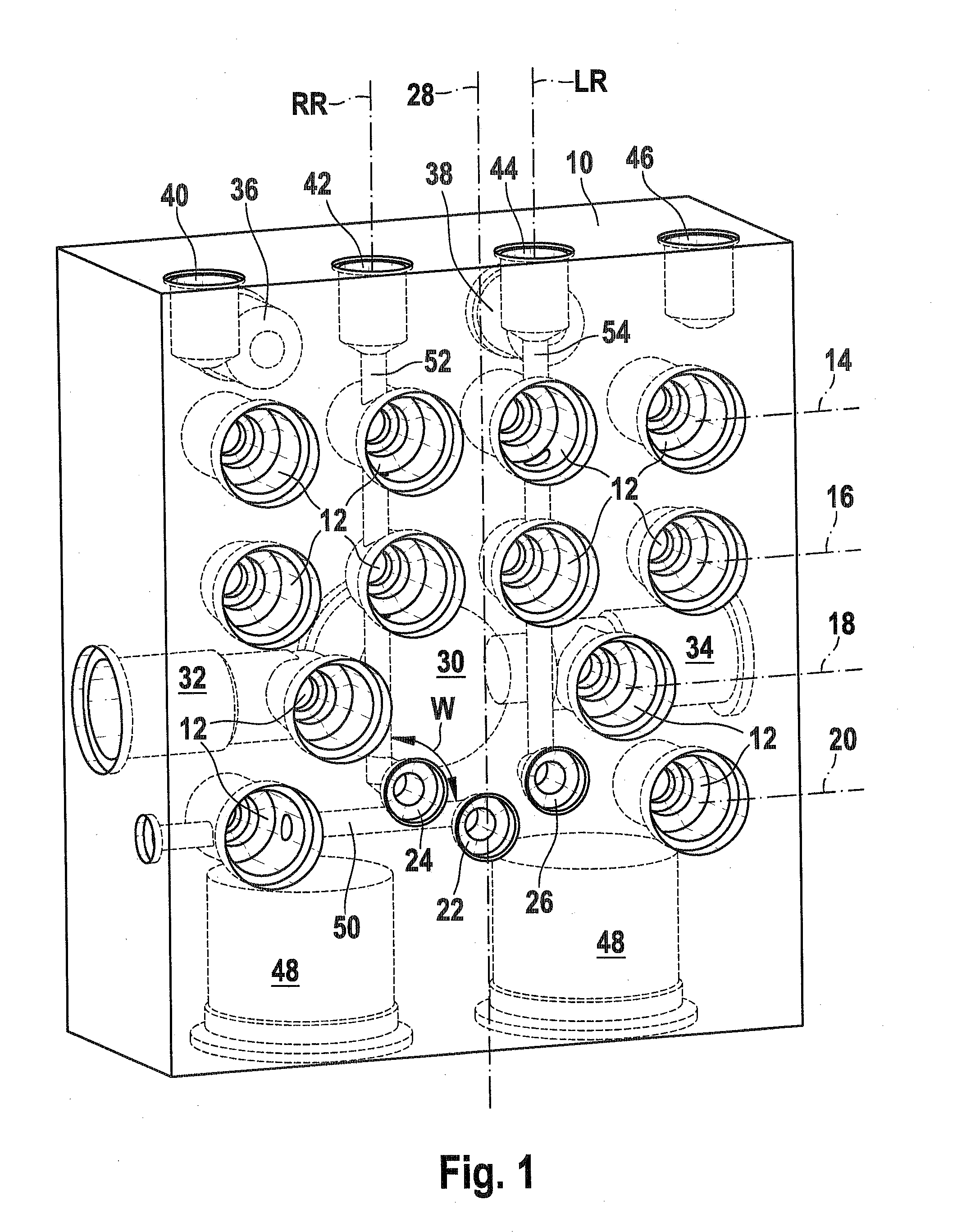
[0011]The housing block 10 of a hydraulic assembly, shown in the drawing, comprises a metal block, in which many recesses have been made by metal-cutting machining. Each of these recesses discharges at one of the exteriors of the housing block 10 and ends in the form of a blind bore in the interior of the housing block 10. The various recesses are hydraulically interconnected to form brake circuits, by means of bores extending horizontally and vertically in the interior of the housing block 10.

[0012]The drawing shows a view at the front side of a housing block 10. This front side may be intended for later securing the electronic control unit to it. A total of twelve identical circular valve bores 12 discharge to the outside at the front side. These valve bores 12 are distributed in four parallel, horizontal rows 14, 16, 18, 20, which are disposed at different levels. In an ensuing assembly process, solenoid valves are inserted into the valve bores 12.

[0013]On the front side of the b...


PUM


Abstract

The invention relates to a hydraulic assembly of a vehicle brake system with traction control. Hydraulic assemblies include a housing block, which is to be fitted with hydraulic components, and an electronic control unit for activating the components. It is known for a hydraulic connection for a pressure sensor to be provided on a housing block and for the signal of the pressure sensor to be taken into consideration for brake pressure regulation in the control unit. The invention proposes an advantageous arrangement of at least one second hydraulic connection for a second pressure sensor on the housing block in combination with blind bores of the hydraulic connections. The blind bores can be positioned in a variable fashion and formed with different lengths during the production of the housing block. In this way, it is possible for the pressure in different hydraulic partial regions of a vehicle brake system to be sensed in an application-specific manner. The number of such hydraulic connections for pressure sensors has no influence on the external dimensions of the housing block.

Description

PRIOR ART[0001]The invention is based on a hydraulic assembly for a vehicle brake system with traction control in accordance with the characteristics of the preamble to claim 1.[0002]Hydraulic assemblies for vehicle brake systems with traction control comprise a housing block and an electronic control unit. The housing block has many recesses for hydraulic components, such as solenoid valves, pumps or reservoirs. Connections for the wheel brakes of a vehicle brake system and for a master cylinder of a vehicle brake system are also embodied on the housing block. Bores in the interior of the housing block make hydraulic connections among these receptacles. The components are typically interconnected in two separate brake circuits. A housing block embodied in this way is known for instance from German Patent Disclosure DE 102 37 163 A1.[0003]The aforementioned electronic control unit evaluates signals from sensors at the wheels of the vehicle, which each detect the prevailing slip cond...

Claims


Application Information

Patent Timeline
IPC IPC(8): B60T17/00
CPCB60T8/368F15B13/086F15B13/0835F15B13/0814
Inventor BAREISS, ALEXANDERWEH, ANDREASIDEGUCHI, TOMOYA
Owner ROBERT BOSCH GMBH
Why Eureka
Try Eureka