Vehicle radar apparatus having variable output power controlled based on speed of vehicle

a technology of vehicle speed and output power, applied in the field of radar equipment, can solve the problems of reducing the energy efficiency of the radar equipment, unable to detect obstacles in the detection area in front of the vehicle, etc., and achieve the effect of increasing the output power, reducing the output power, and effectively controlling the power consumption

Inactive Publication Date: 2010-11-04
DENSO CORP
View PDF2 Cites 64 Cited by
  • Summary
  • Abstract
  • Description
  • Claims
  • Application Information

AI Technical Summary

Benefits of technology

[0021]According to the above-described invention, a technique used to adjust the output power of the radar apparatus is exemplified. Specifically, adjusting the modulation period longer or adjusting the number of modulations larger, allow the radar output power to increase. Conversely, adjusting the modulation period shorter or adjusting the number of modulations smaller allows the output power to decrease.
[0022]According to the seventh aspect of the present invention, the radar apparatus is configured to control the power supplied to the monolithic micro integrated circuit ON/OFF in response to a change of the modulation period and/or a change of the numb

Problems solved by technology

However, to detect obstacles reliably while the vehicle is running, the radar apparatus usually operates with a large output power so that the energy efficiency

Method used


Image

  • Vehicle radar apparatus having variable output power controlled based on speed of vehicle
  • Vehicle radar apparatus having variable output power controlled based on speed of vehicle
  • Vehicle radar apparatus having variable output power controlled based on speed of vehicle

Examples


first embodiment

[0042]With reference to FIGS. 1 to 8, hereinafter will be described a first embodiment according to the present invention.

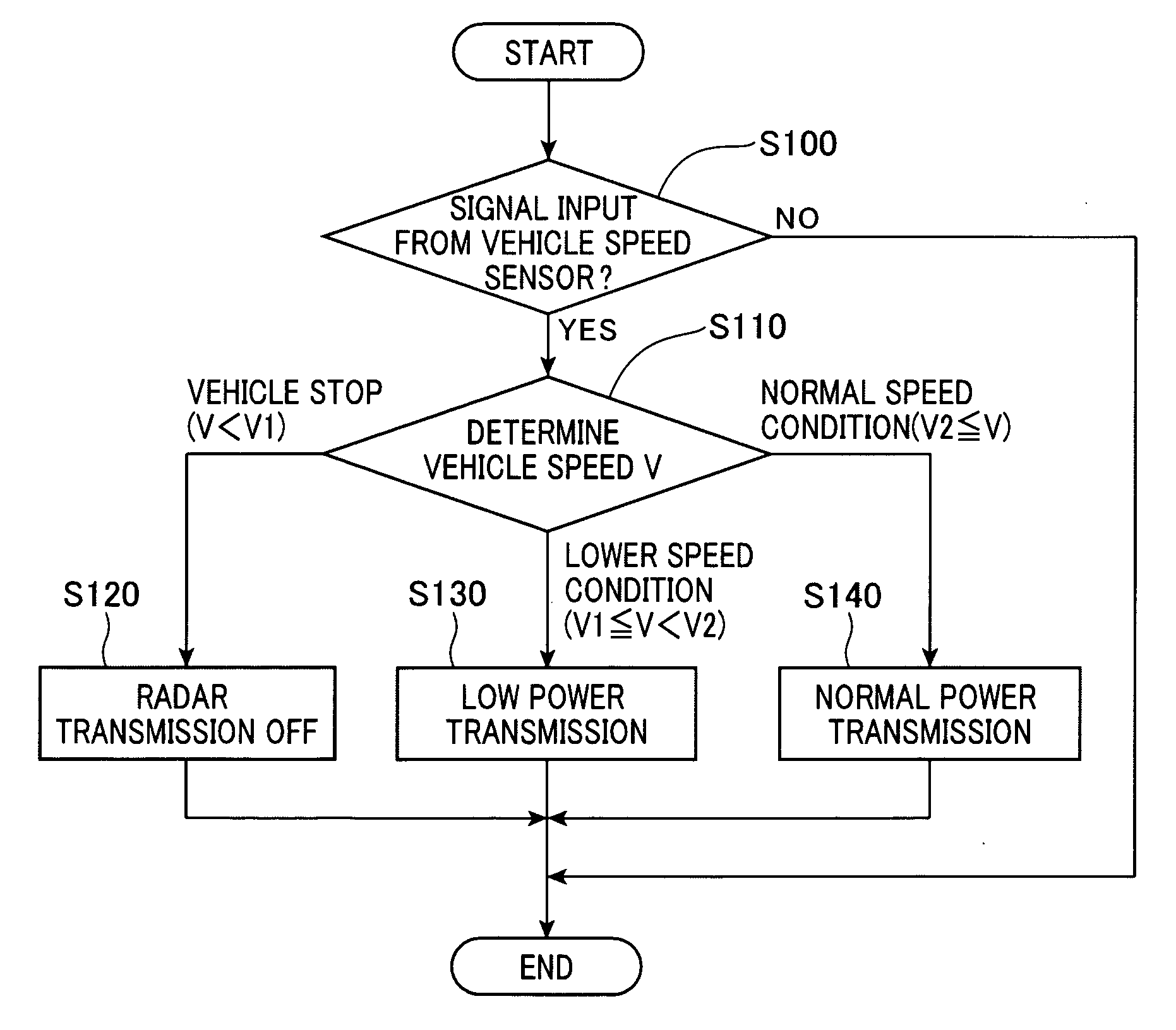
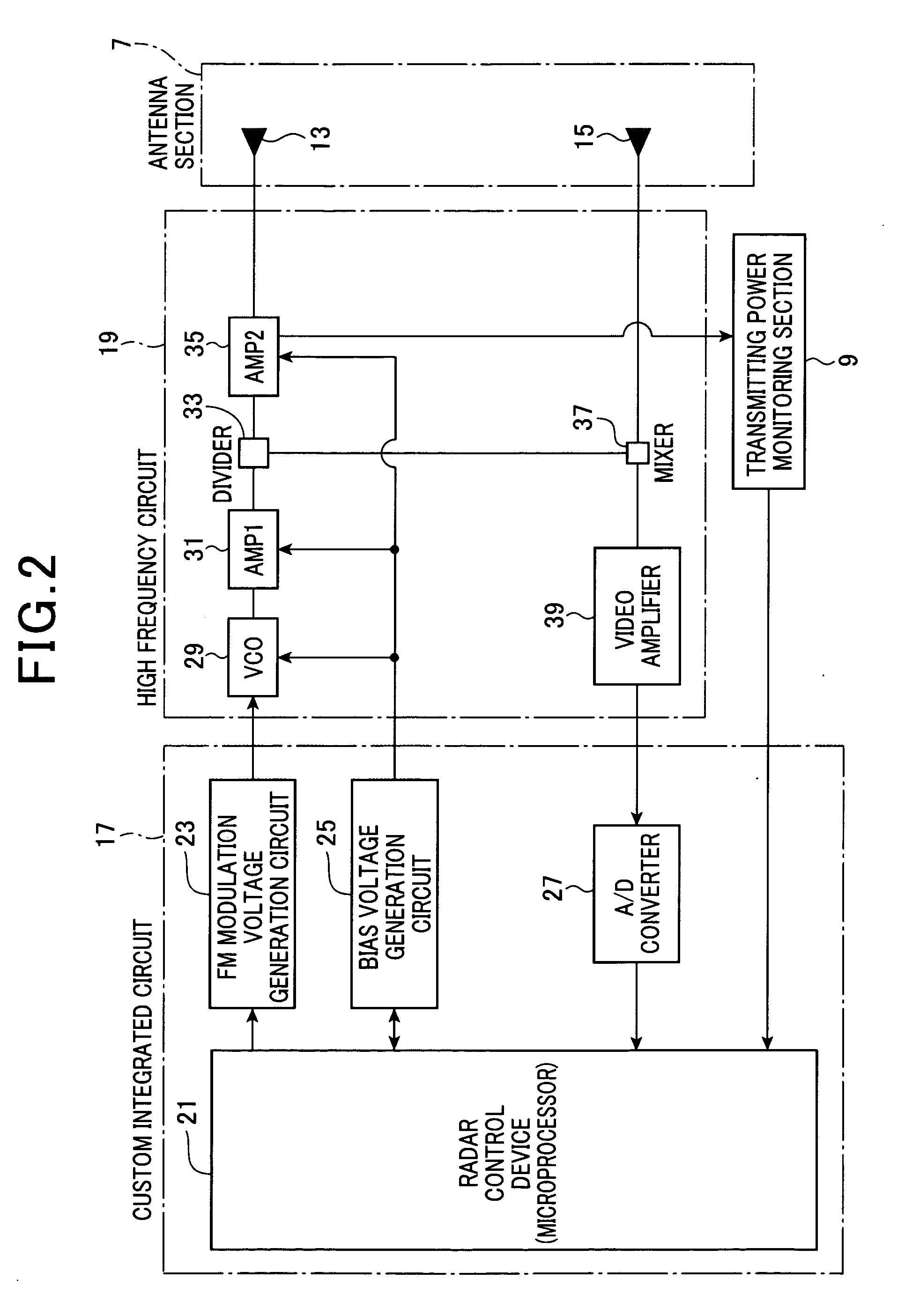
The radar apparatus according to the present invention controls the transmitting power of the radar apparatus in response to the vehicle speed. In addition, the radar apparatus is configured to have a function that monitors whether or not the transmitting power of the radar apparatus is within a target range.[0043]a) First, a general configuration of a vehicle system including the radar apparatus of the first embodiment is described as follows.

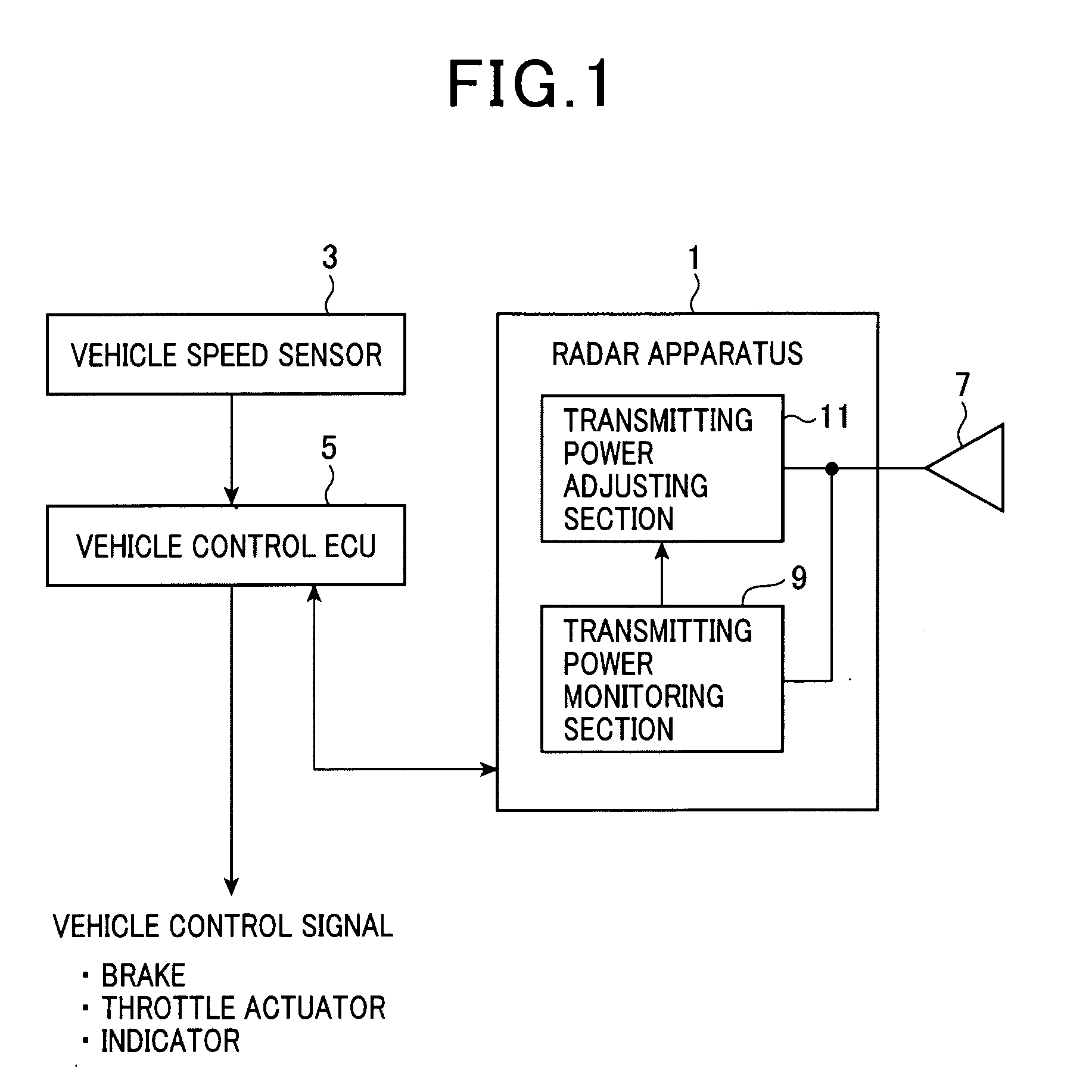
[0044]As shown in FIG. 1, the vehicle provided with a radar apparatus 1, a vehicle speed sensor 3 and a vehicle control unit 5 i.e., vehicle control ECU (Electronic Control Unit). The radar apparatus 1 detects a running speed concerning a preceding vehicle that is running ahead of the own vehicle or a distance to the preceding vehicle and the like. The vehicle speed sensor 3 detects the running speed of the own vehicle and ...

second embodiment

[0096]With reference to FIGS. 9 to 10A-10C, hereinafter will be described the second embodiment. However, explanations of which contents similar to the first embodiment are omitted. In the second embodiment, the control procedure of the radar transmitting power differs from the first embodiment. As shown in FIG. 9, a major portion of the radar apparatus according to the second embodiment is shown. The radar control device 101 includes a controller 103 and a memory section 105. A FM modulation voltage generation circuit 107 which is connected to the radar control device 101 outputs triangular waves which is sent to a VCO 109 of the MMIC.

Specific procedures for adjusting the radar transmitting power are described as three types of procedures a) to c) as follows. Here is described a procedure in which the transmitting power when the vehicle is in the normal speed condition is switched to the transmitting power when the vehicle is in lower speed condition.

FMCW Modulation A

[0097]As shown...

third embodiment

[0103]With reference to FIGS. 11 to 13, hereinafter will be described the third embodiment. However, explanations of which contents similar to the first embodiment are omitted. In the third embodiment, the radar transmitting power of the radar apparatus is monitored and the radar transmitting power is controlled in response to the vehicle speed.[0104]a) First, a configuration used for monitoring the transmitting power and controlling the transmitting power which are features of the present invention is described as follows. As shown in FIG. 11, as similar to the first embodiment, a high frequency board 111 includes a VCO 113, an amplifier (AMP 1) 115, a divider 117, an amplifier (AMP 2) 119, transmission antenna 121 and the like.

As shown in FIG. 11, a transmitting power monitoring section 123 includes a detection diode 125, a differential amplifier 126 and the like. In the transmitting monitoring section 123, the transmitting power (transmission voltage) from the amplifier 119 of th...


PUM


Abstract

A vehicle radar apparatus that controls millimeter-wave radar operation is provided. The radar apparatus is configured to control the radar operation based on the speed of the vehicle. In the radar apparatus, the vehicle speed is detected and the output power of the radar apparatus (radar output power) is controlled such that the radar output power is set with at least two different output power levels in response to the vehicle speed.

Description

CROSS REFERENCE TO RELATED APPLICATION[0001]This application is based on and claims the benefit of priority from earlier Japanese Patent Application No. 2009-112154 filed May 1, 2009, the description of which is incorporated herein by reference.BACKGROUND OF THE INVENTION[0002]1. Field of the Invention[0003]The present invention relates to a radar apparatus, more particularly to a radar apparatus that controls millimeter-wave radar.[0004]2. Description of the Related Art[0005]Conventionally, vehicle control units that automatically control a running state of the vehicle have been developed. For instance, a cruise control unit that controls vehicle speed to be constant and an adaptive cruise control unit that tracks a preceding vehicle by maintaining a predetermined distance to the preceding vehicle are known.[0006]Specifically, patent documents, e.g. Japanese patent application laid-open numbers 1999-342766, 1997-324666 and 1999-268558 disclose a vehicle control unit that controls t...

Claims


Application Information

Patent Timeline
IPC IPC(8): G01S13/88G01S13/931
CPCG01S7/03G01S7/4008G01S2013/9353G01S13/931G01S13/34G01S2013/932
Inventor ANDO, TAKAMASA
Owner DENSO CORP
Why Eureka
Try Eureka