Optoelectronic methods and devices for detection of analytes

Active Publication Date: 2010-11-04
3M INNOVATIVE PROPERTIES CO
View PDF28 Cites 50 Cited by
  • Summary
  • Abstract
  • Description
  • Claims
  • Application Information

AI Technical Summary

Benefits of technology

[0007]In another aspect, herein is disclosed an optoelectronic device for monitoring an analyte in an atmosphere, comprising: a housing at least partially defining an interior space and containing at an opening; at least one sensing element secured in the opening of the housing; and, in the interior space, at least one light sourc

Problems solved by technology

Moreover, many of these systems have lifetime limitation issues, due to photo-bleaching or undesirable side reactions.
Many such systems also rely on complicated or bulky optoelectronic components to carry out the optical interrogation.

Method used


Image

  • Optoelectronic methods and devices for detection of analytes
  • Optoelectronic methods and devices for detection of analytes
  • Optoelectronic methods and devices for detection of analytes

Examples


example

[0099]A 3M Model 110 Carbon Monoxide Monitor from 3M Company, St. Paul Minn. was disassembled and the electronic components removed therefrom with the exception of the liquid crystal display. A printed circuit board was designed of the proper size, and bearing suitable connections, so as to fit into the housing of the 110 Monitor and to interface with the LCD display via zebra strip connections. The printed circuit board was custom designed to receive, support, and electrically connect, the various components discussed hereafter.

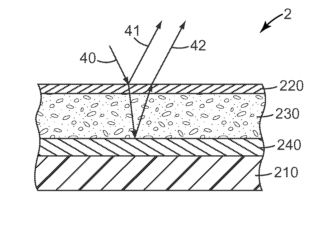
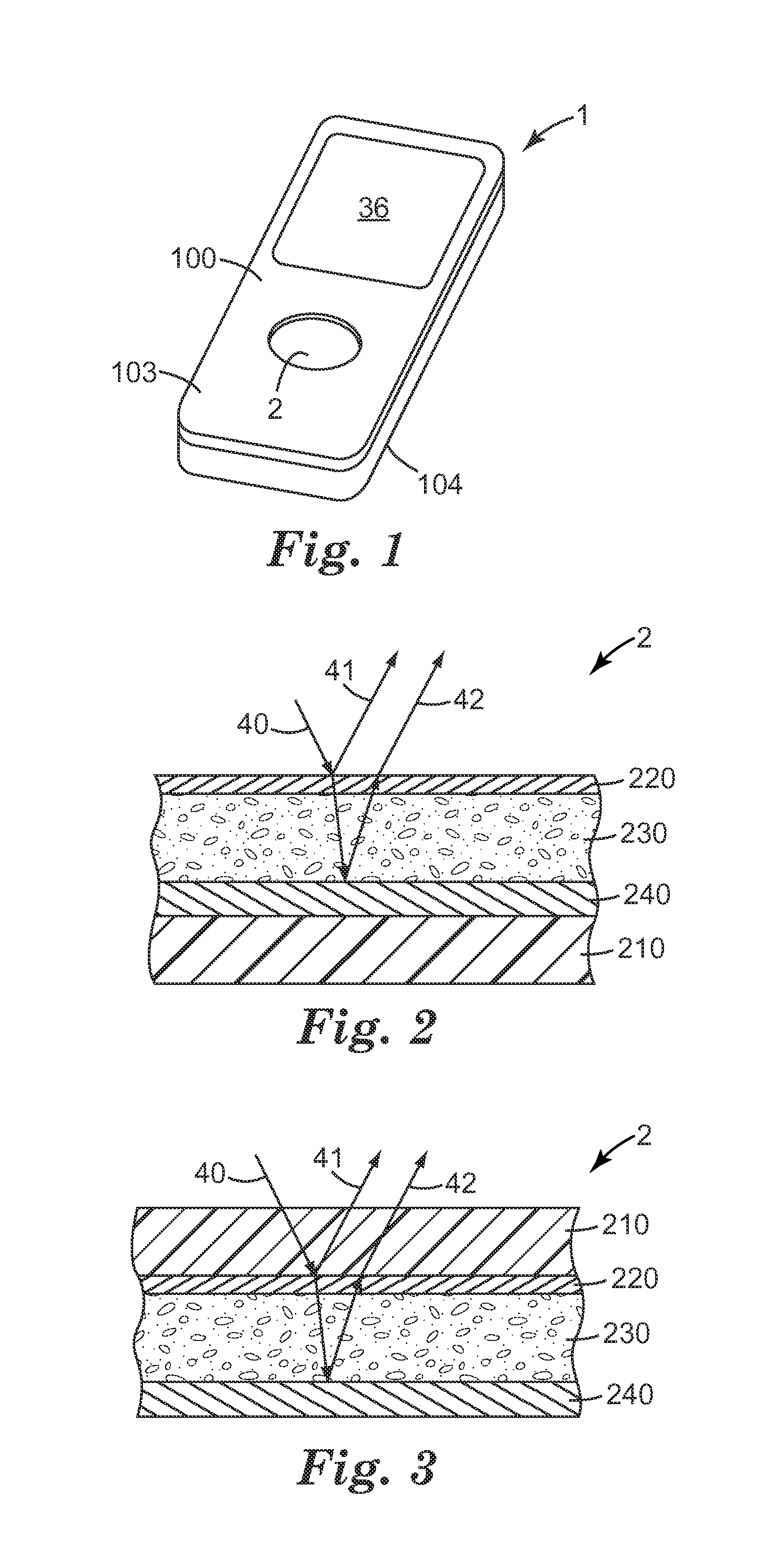
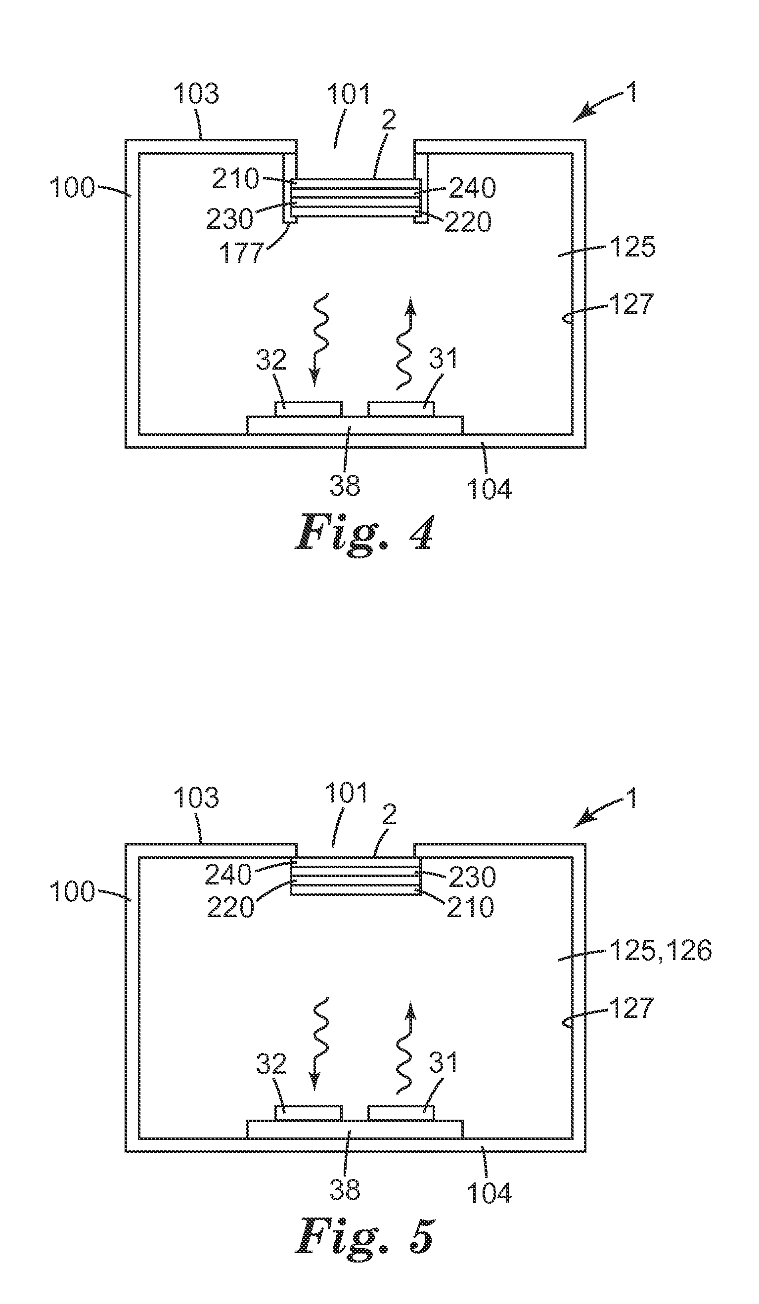
[0100]Upon the printed circuit board were mounted a photodiode (SFH 2430, OSRAM, Regensburg, Germany). The printed circuit board and the location of the photodiode were chosen so that when the printed circuit board was secured in the 110 housing, a sensing element was placed in the opening of the 110 housing, and the two halves of the housing were fitted together, the photodiode was facing the sensing element and positioned in alignment with the normal axis ...


PUM


Abstract

Herein are disclosed optoelectronic methods and devices for detecting the presence of an analyte. Such methods and devices may comprise at least one sensing element that is responsive to the presence of an analyte of interest and that may be interrogated optically by the use of at least one light source and at least one light detector.

Description

CROSS REFERENCE TO RELATED APPLICATIONS [0001]This application claims the benefit of U.S. Provisional Application No. 61 / 164,496, filed Mar. 30, 2009, which is incorporated herein by reference in its entirety.BACKGROUND [0002]The ability to detect chemical analytes, especially organic chemical analytes, is important in many applications, including environmental monitoring and the like. Such detection and / or monitoring of analytes may find particular use in, for example, personal monitors (e.g., that can be worn or carried by a person), and / or area monitors (e.g., that can be placed in a desired environment).[0003]Many methods for the detection of chemical analytes have been developed, for example optical, gravimetric, microelectromechanical, and colorimetric. Though colorimetric devices currently exist for a range of analytes, most are based upon employing dyes or colored chemical indicators for detection. Such compounds are typically selective, meaning that multiple sensors may be ...

Claims


Application Information

Patent Timeline
IPC IPC(8): G01N21/55
CPCG01N21/274G01N2021/3155G01N21/55G01N21/783B33Y80/00G01N21/8483C03C2217/425
Inventor HULTEEN, JOHN C.KANUKURTHY, KIRAN S.RAKOW, NEAL A.RYBACHA, ANDRZEJ F.RYLANDER, RICHARD L.SCHEFFLER, ARTHURZUPANC, ZELJKO
Owner 3M INNOVATIVE PROPERTIES CO
Why Eureka
Try Eureka