Light collection and illumination systems employing planar waveguide

a planar waveguide and light collection technology, applied in the field of optical reflection devices, can solve the problems of affecting the utility of devices, requiring a fairly complex structure, and occupying substantial volume, and achieve the effect of facilitating light transport and harvesting

Active Publication Date: 2010-11-04
S V V TECH INNOVATIONS
View PDF46 Cites 430 Cited by
  • Summary
  • Abstract
  • Description
  • Claims
  • Application Information

AI Technical Summary

Benefits of technology

[0044]In at least one implementation, at least one optically responsive electronic device is coupled to at least one of the first terminal edge or the second terminal edge of the planar waveguide. In at least one implementation, the electronic device can be optically coupled to a cutout within the planar waveguide. In at least one implementation, any optional cladding or protective coatings are removed from the light harvesting area, such as from the first or second terminal edge, and / or the first or second side wall, to facilitate light transport and harvesting in the harvesting area.

Problems solved by technology

These devices collect energy in a broad spectrum from the entire area of the device and focus it onto a smaller area disposed at a considerable distance above or beneath the device and requires a fairly complex structure which occupies substantial volume.
Although the light guides themselves are typically slim and space efficient, the additional optics necessary for collecting or distributing the light over a large area leads to increased cost and system volume.
In response to these shortcomings, the utility of the devices is hampered while numerous spatially-sensitive applications are rendered impractical.
However, because of the scattered nature of the reradiated light, only a portion of it can become trapped in the light guide by the total internal reflection, while the rest of the light escapes from the light guide.
Furthermore, the luminescent centers can absorb or scatter already trapped light thus making the light guide less transparent and less efficient.
However, at least a portion of the diffracted light is lost at each bounce from the same holographic layer guide due to re-coupling.
None of the previous efforts provides an efficient solution for light collection or concentration into a waveguide through its longitudinal face while maintaining a low system profile.
These devices are fairly bulky structures occupying substantial volume.
This increases system size, weight, and cost, while hampering utility of the system.
The inclusion of additional optics increases cost and system volume rendering the designs impractical in space-limited applications.
Although this latter approach is more space efficient than the former one, the light comes out of the waveguide substantially uncollimated due to the inherent divergence of the light propagating in the waveguide which results in the substantial divergence of light extracted from the waveguide.
Use of these light sources often results in unwanted glare problems, particularly in some general lighting applications or display lights.
Accordingly, prior illumination efforts have failed to provide an efficient solution for extracting light from a waveguide through its longitudinal face with efficient light collimation.

Method used


Image

  • Light collection and illumination systems employing planar waveguide
  • Light collection and illumination systems employing planar waveguide
  • Light collection and illumination systems employing planar waveguide

Examples


embodiment 2

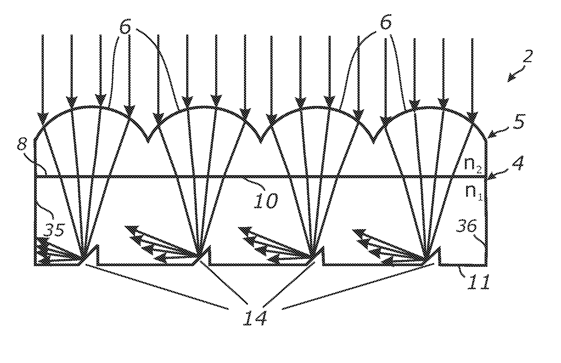
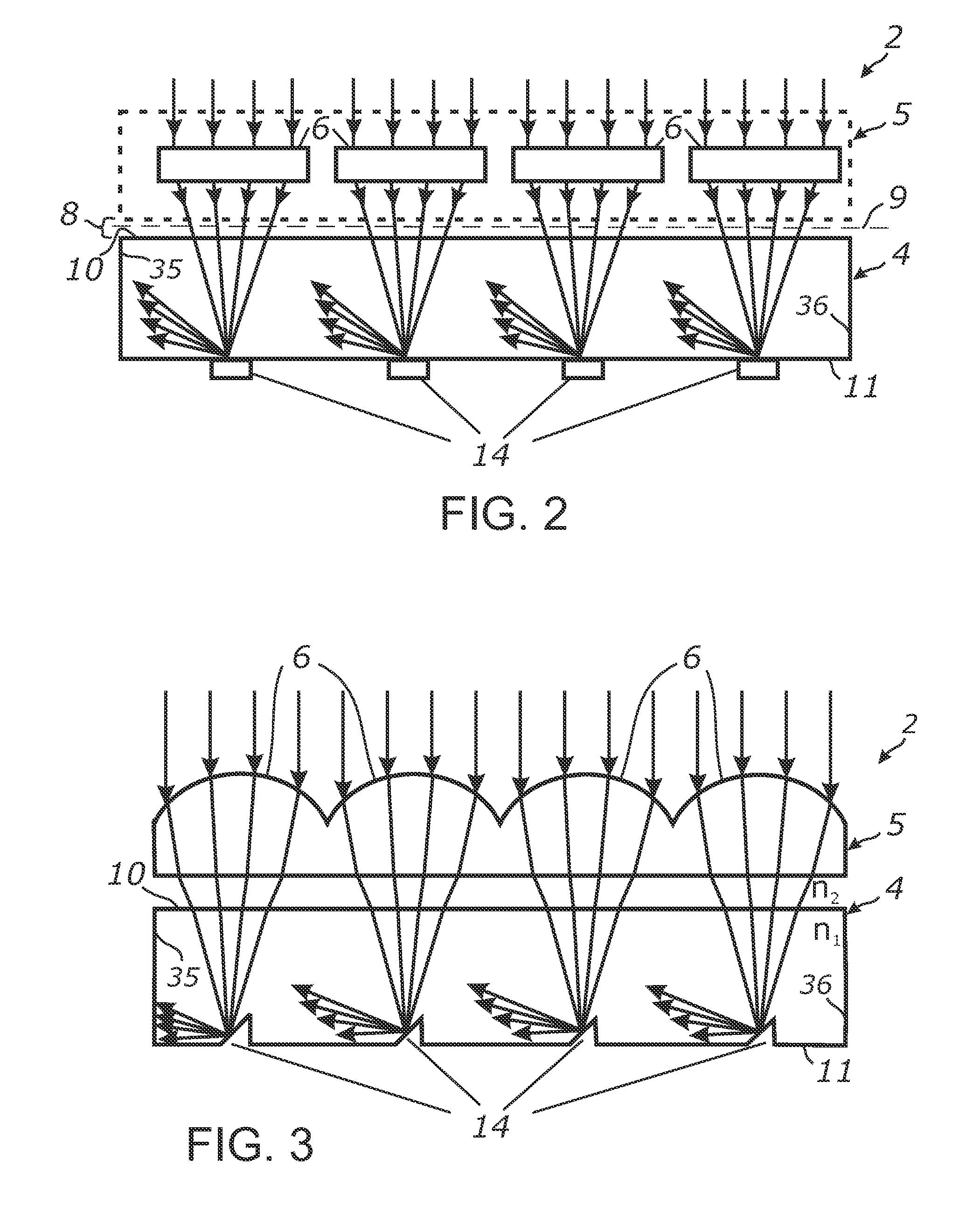
[0130]A suitable optical interface 8 can be created by various mechanisms. For example, when the total internal reflection is used for trapping the light in waveguide 4, interface 8 may comprise a physical boundary or wall of the body of waveguide 4 which is surrounded by outside media with lower refractive medium such as air. Alternatively, it can be an interface between two media having different refractive indices so that the refractive index increases along the optical path from focusing means 6 toward waveguide 4. Interface 8 can be implemented by separating waveguide 4 from the body of collector array 5 or from bodies of individual focusing means 6 by means of a thin layer of air, a layer of lower refractive index dielectric medium or any other boundary between a higher refractive index medium and a lower refractive index medium. In a more specific example, interface 8 can be implemented from an interface between glass, PMMA or polycarbonate (high refractive index) and a low r...

embodiment 1

[0287]2. The apparatus of embodiment 1, wherein said plurality of light collimating elements comprises a parallel array of elongated lenticular lenses.

[0288]3. The apparatus of embodiment 1, wherein said plurality of light collimating elements comprises a parallel array of elongated focus mirrors.

[0289]4. The apparatus of embodiment 1, wherein said plurality of light deflecting elements comprises a parallel array of elongated grooves.

[0290]5. The apparatus of embodiment 1, wherein said plurality of light deflecting elements comprises a parallel array of elongated grooves; wherein said grooves are configured at a slope angle which is bounded by the relation in which is the refractive index of the planar waveguide and is the refractive index of the collimator array.

[0291]6. The apparatus of embodiment 1, wherein said plurality of light deflecting elements comprises grooves within said planar waveguide configured for redirecting the received light in response to reflection from at leas...

embodiment 32

[0318]33. The apparatus of embodiment 32, wherein said plurality of light collecting elements comprises a parallel array of elongated focus mirrors.

[0319]34. The apparatus of embodiment 32, wherein said plurality of light collecting elements comprises a parallel array of elongated lenticular lenses.

[0320]35. The apparatus of embodiment 32: wherein said plurality of light deflecting elements comprises a parallel array of elongated grooves.

[0321]36. The apparatus of embodiment 32: wherein said plurality of light deflecting elements comprises a parallel array of elongated grooves; wherein said grooves are configured at a slope angle θ30 which is bounded by the relation

arcsin(n2n1)≤θ30≤arccos(n2n1)

in which n1 is the refractive index of the planar waveguide and n2 is the refractive index of the collimator array.

[0322]37. The apparatus of embodiment 32, wherein said plurality of light deflecting elements comprises grooves within said planar waveguide configured for redirecting the receive...


PUM


Abstract

An apparatus for distributing light from a waveguide through a collimating array, or collecting light over a given area into a waveguide. Light received within a waveguide is propagated transmissively and retained by total internal reflection, except in response to impinging upon deflector elements which sufficiently redirect the light to escape the waveguide into a collimator array that aligns and distributes the light. In a light collector, a collection array collects and collimates the received light and directs it at the surface of a waveguide, within which deflectors properly positioned in relation to each collector of the collector array, deflect the angle of the light so that it propagates through the waveguide in response to total internal reflection. The apparatus can be fabricated into an efficient and compact form.

Description

CROSS-REFERENCE TO RELATED APPLICATIONS[0001]This application claims priority from U.S. provisional application Ser. No. 61 / 214,331 filed on Apr. 21, 2009, incorporated herein by reference in its entirety, and from U.S. provisional application Ser. No. 61 / 339,512 filed on Mar. 6, 2010, incorporated herein by reference in its entirety.STATEMENT REGARDING FEDERALLY SPONSORED RESEARCH OR DEVELOPMENT[0002]Not ApplicableINCORPORATION-BY-REFERENCE OF MATERIAL SUBMITTED ON A COMPACT DISC[0003]Not ApplicableNOTICE OF MATERIAL SUBJECT TO COPYRIGHT PROTECTION[0004]A portion of the material in this patent document is subject to copyright protection under the copyright laws of the United States and of other countries. The owner of the copyright rights has no objection to the facsimile reproduction by anyone of the patent document or the patent disclosure, as it appears in the United States Patent and Trademark Office publicly available file or records, but otherwise reserves all copyright right...

Claims


Application Information

Patent Timeline
Patent Type & Authority Applications(United States)
IPC IPC(8): G02B6/32
CPCG02B3/005G02B3/0056G02F1/133605G02B6/0038G02B6/0053H01L31/0547G03B21/208G02F2001/133607G02F2001/133628H01L31/0549G03B21/2066Y02E10/52G02F1/133628G02F1/133607G02B6/0063G02B6/0003G02B6/0055
Inventor VASYLYEV, SERGIY V.
Owner S V V TECH INNOVATIONS
Why Eureka
Try Eureka