System and Method for Directed Self-Assembly Technique for the Creation of Carbon Nanotube Sensors and Bio-Fuel Cells on Single Plane
What is Al technical title?
Al technical title is built by PatSnap Al team. It summarizes the technical point description of the patent document.
a carbon nanotube and self-assembly technology, applied in the field of nanotubes, can solve the problem of controlled number(s) in the fabrication of carbon nanotube devices, and achieve the effect of improving the system and method of fabricating nanotube devices
Inactive Publication Date: 2010-11-04
NEW JERSEY INSTITUTE OF TECHNOLOGY
View PDF34 Cites 15 Cited by
Summary
Abstract
Description
Claims
Application Information
AI Technical Summary
This helps you quickly interpret patents by identifying the three key elements:
Problems solved by technology
Method used
Benefits of technology
[0007]The present disclosure provides advantageous nanotube devices, and improved systems and methods for fabricating nanotube devices. More particularly, the present disclosure provides advantageous systems and methods for depositing controlled numbers of CNTs (e.g., vertically aligned CNTs) with specific properties (e.g., including orientation) at predefined locations for use with and / or for the fabrication of CNT devices. For example, the nanotube devices of the present disclosure may be utilized in a wide range of applications, including, for example, as improved biomedical devices, energy cells, integrated circuits (ICs), three-dimensional circuits, transistors, bio-molecular detectors, sensors, and / or bio-fuel cells. For example, bio-fuel cells engineered on a molecular scale may provide a continuously renewable, tailored power source for a wide range of applications, including, for example, targeted drug delivery, physiological monitoring and control, synthetic organs, prostheses, and other advanced medical devices (e.g., pacemakers, insulin pumps, glucose and pressure sensors, and bionic devices for stimulating the brain and spinal cord).
Problems solved by technology
One of the most difficult problems in the fabrication of carbon nanotube (CNT) devices is the deposition of controlled number(s) of CNTs with specific properties (e.g., including orientation) at predefined locations.
Method used
Image
Click on the blue label to locate the original text in one second.
Reading with bidirectional positioning of images and text.
Examples
example 1
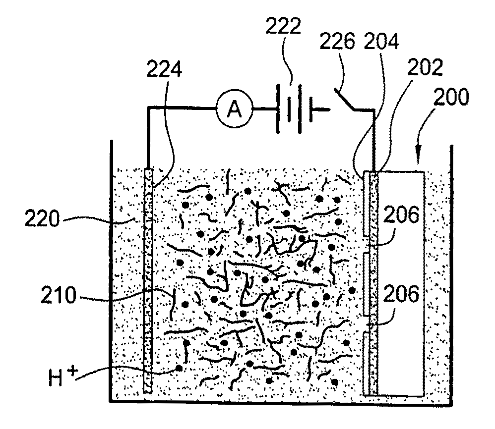
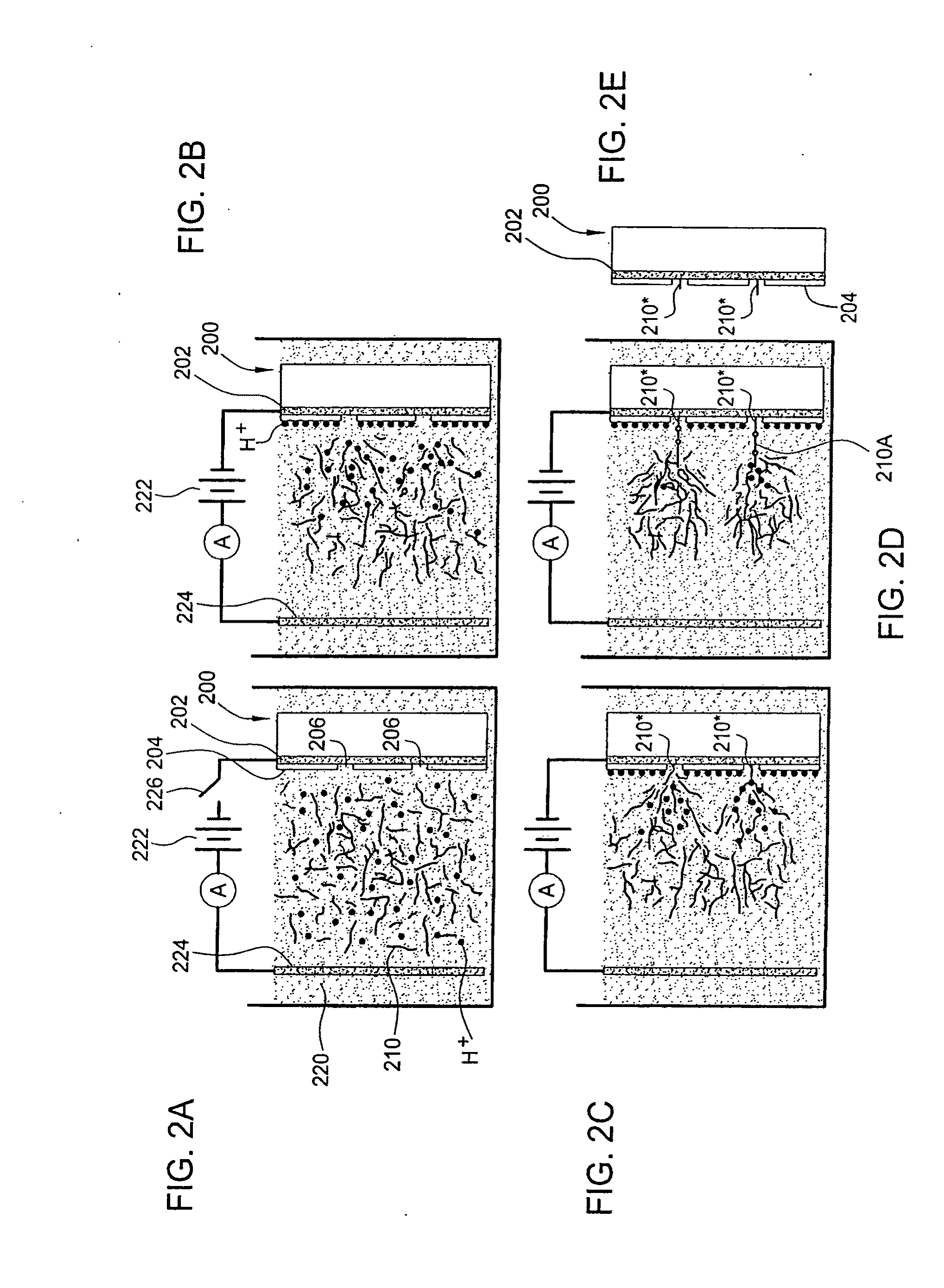
[0108]The substrates for the deposition of carbon nanotubes were 100 mm silicon wafers. Layers of silicon nitride and silicon oxide were deposited using plasma enhanced chemical vapor deposition. Photolithography was used to pattern the micro-rails in OIR620-7i / LOR 3A photoresist with a GCA Autostep stepper. A Cr / Co metal layer (20 nm Cr / 200 nm Co) was deposited using an e-beam evaporator. The metal in the unpatterned areas was “lifted-off” by dissolving the resist. An approximately 75 nm thick layer of silicon nitride was then deposited using plasma enhanced chemical vapor deposition (PECVD) followed by evaporation of about 50 nm amorphous carbon and about 5 nm silicon oxide. Six windows or apertures were patterned on each micro-rail using ZEP520A resist and a Jeol 9300FS electron-beam lithography system. Along with the windows on the micro-rails, test patterns were printed on a separate metal pad for diagnostics to help optimize the e-beam lithography and electrophoresis depositio...
PUM
Property
Measurement
Unit
diameter
aaaaa
aaaaa
diameter
aaaaa
aaaaa
diameter
aaaaa
aaaaa
Abstract
Improved nanotube devices and systems/methods for fabrication thereof are provided. The present disclosure provides systems/methods for depositing controlled numbers of nanotubes with specific properties at predefined locations for the fabrication of nanotube devices. The nanotube devices may be utilized in a range of applications. A bio-fuel cell system that does not require a proton exchange membrane separator and does not need a mediator to transfer charge is provided. This exemplary bio-fuel cell uses enzyme functionalized SWNTs for the anode/cathode. The absence of a membrane in the bio-fuel cell configuration opens up the possibility of other configurations that would otherwise be unfeasible. This includes a bio-fuel cell where the anode/cathode are on the same substrate. Since the electrodes can share the same substrate, the configuration may be integrated with a circuit device on the same substrate. An IC and its power source may be fabricated on the same silicon wafer.
Description
CROSS REFERENCE TO RELATED APPLICATIONS[0001]This application claims the benefit of U.S. Provisional App. Nos. 61 / 160,065, filed Mar. 13, 2009, and 61 / 237,339, filed Aug. 27, 2009, both of which being herein incorporated by reference in their entireties; and claims priority to and is a continuation-in-part of co-pending U.S. patent application Ser. Nos. 11 / 765,788 and 11 / 765,735, filed Jun. 20, 2007, both of which being herein incorporated by reference in their entireties.STATEMENT OF GOVERNMENT RIGHTS[0002]The work described in this patent disclosure was sponsored by the U.S. Department of Defense's Defense Advanced Research Projects Agency (“DARPA”) grants FA9550-05-1-0461, FA8650-08-1-7825 and N00014-08-1-0278.TECHNICAL FIELD[0003]The present disclosure generally relates to the fields of nanotubes (e.g., carbon nanotubes), nanotube devices, electrophoresis, three-dimensional circuits, nanofabrication, transistors, bio-molecular detectors, bio-sensors, and / or bio-fuel cells. More ...
Claims
Application Information
Patent Timeline
Application Date:The date an application was filed.
Publication Date:The date a patent or application was officially published.
First Publication Date:The earliest publication date of a patent with the same application number.
Issue Date:Publication date of the patent grant document.
PCT Entry Date:The Entry date of PCT National Phase.
Estimated Expiry Date:The statutory expiry date of a patent right according to the Patent Law, and it is the longest term of protection that the patent right can achieve without the termination of the patent right due to other reasons(Term extension factor has been taken into account ).
Invalid Date:Actual expiry date is based on effective date or publication date of legal transaction data of invalid patent.
Patent Type & Authority Applications(United States)