Method and Device for Controlling at Least One Glow Plug of a Motor Vehicle

a technology of motor vehicles and glow plugs, which is applied in the direction of electric control, machines/engines, instruments, etc., can solve the problems of increasing smoke emissions and affecting the life span of glow plugs as little as possible, so as to prevent overheating of glow plugs or even damage to glow plugs, the effect of sufficient thermal support of combustion process, and sufficient energy supply to glow plugs

Active Publication Date: 2010-11-04
ROBERT BOSCH GMBH
View PDF4 Cites 14 Cited by
  • Summary
  • Abstract
  • Description
  • Claims
  • Application Information

AI Technical Summary

Benefits of technology

[0004]During the glowing, the controlling of the glow plugs takes place dependent on the operating parameters of the internal combustion engine, such as in particular the engine rotational speed, the fuel quantity, the external temperature, and / or the exhaust gas temperature. In this way, sufficient energy can be supplied to the glow plugs to achieve a sufficient thermal support of the combustion process. In addition, however, the unnecessary supplying of energy to the glow plugs, which could result in an overheating of the glow plugs or even damage to the glow plugs, is prevented.

Problems solved by technology

If an injection with a higher fuel quantity subsequently takes place, this results in increased smoke emissions.
Preferably, the magnitude and gradient of the preheating are designed to be moderate enough that the life span of the glow plugs is adversely affected as little as possible.

Method used


Image

  • Method and Device for Controlling at Least One Glow Plug of a Motor Vehicle
  • Method and Device for Controlling at Least One Glow Plug of a Motor Vehicle
  • Method and Device for Controlling at Least One Glow Plug of a Motor Vehicle

Examples


Embodiment Construction

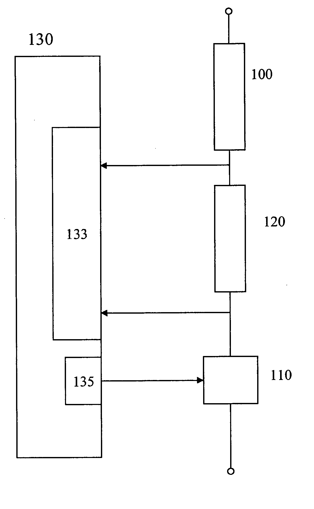
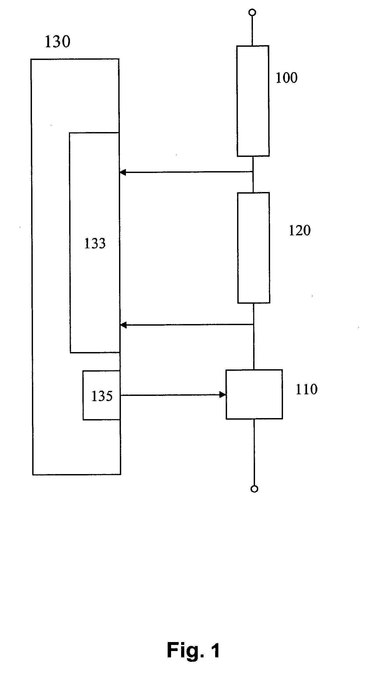
[0008]In FIG. 1, the important elements of the device according to the present invention are shown. A glow plug 100 is connected in series with a current measuring device 120 and a switching device 110, between the two terminals of a voltage supply. In the depicted exemplary embodiment, for each glow plug there is provided one current measuring device 120 and one switching device 110. An embodiment of the device according to the present invention can also be designed such that a common switching device and / or a common current measuring device is provided for a plurality of glow plugs of an internal combustion engine, or for all glow plugs of an internal combustion engine.

[0009]The depicted specific embodiment, in which each glow plug is allocated one current measuring device 120 and one switching device 110, offers the advantage that the glow plug can be controlled individually and the current flowing through the glow plug can be evaluated. If a plurality of glow plugs are combined ...


PUM


Abstract

A device and a method for controlling at least one glow plug of a motor vehicle are described. The at least one glow plug is controlled as a function of the operating state of the internal combustion engine. In this case, the control is effected as a function of a variable which depends on the exhaust gas temperature and/or as a function of the fulfillment of a fuel quantity condition and/or time condition.

Description

BACKGROUND INFORMATION[0001]Standardly, the glow plugs are used to heat the combustion chambers when the internal combustion engine is started. The controlling of the at least one glow plug takes place dependent on the operating state of the internal combustion engine.SUMMARY OF THE INVENTION[0002]According to the present invention, it is recognized that in certain operating states the exhaust gas emissions can be significantly reduced if the controlling of the glow plugs takes place dependent on a quantity that is dependent on the exhaust gas temperature and / or on the fulfillment of a fuel condition.[0003]Thus, the smoke emissions can be significantly reduced in particular in the case of a change in engine operation when the motor is cool. In particular, the white smoke and / or black smoke can be significantly reduced during the transition from overrun operation to normal driving operation. According to the present invention, it is recognized that in longer overrun operation or long...

Claims


Application Information

Patent Timeline
Patent Type & Authority Applications(United States)
IPC IPC(8): F02D28/00
CPCF02D41/123F02D41/126F02P19/026F02D2041/1411F02D41/1446F02P19/02F02D41/12F02D41/14
Inventor MORITZ, RAINERDRESSLER, WOLFGANGJANZEN, EBERHARD
Owner ROBERT BOSCH GMBH
Why Eureka
Try Eureka