
Low emissive radiant barrier flex (LOW-E FLEX)

a radiant barrier and low emissive technology, applied in the field of low emissive radiant barrier flex (lowe flex), can solve the problems adding a layer of less permeable and less penetrated material to the outer coil, etc., and achieves the effect of reducing heat loss/gain and reducing heat transfer

Inactive Publication Date: 2010-11-11
SAWYER SCOTT
View PDF20 Cites 9 Cited by
  • Summary
  • Abstract
  • Description
  • Claims
  • Application Information

AI Technical Summary

Benefits of technology

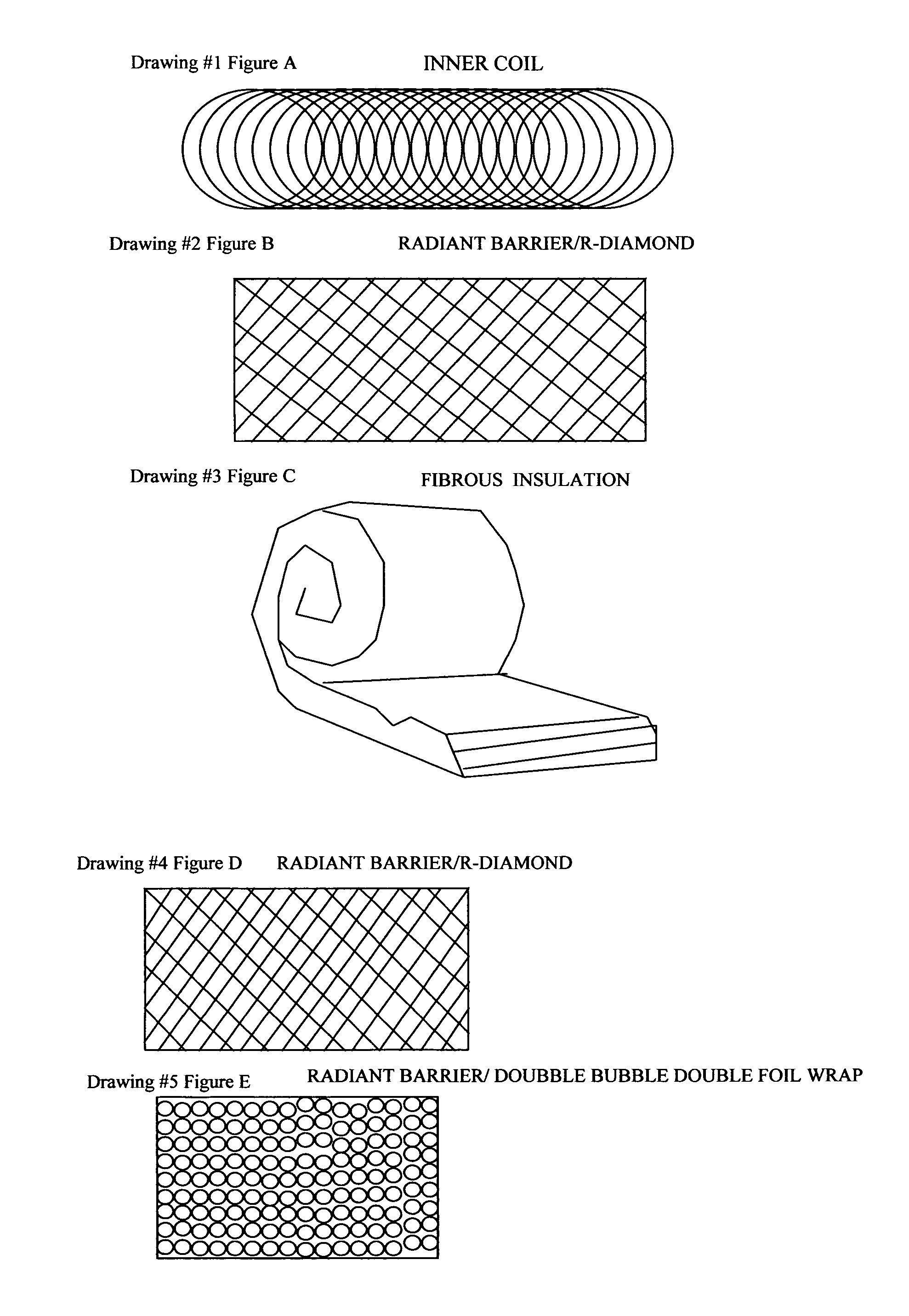
[0009]What is radiant barrier? Radiant barriers or reflective barriers work by reducing heat transfer by thermal radiation. They are highly reflective, low emittance materials currently energy star approved for decreasing the heat loss / gain of structures when applied to the attic and / or roof. The two most common types of radiant barriers used are radiant double bubble double foil and r-diamond.
[0010]What Benefit would radiant technology add to flex duct? With research, it has been proven that wrapping ductwork with a radiant barrier significantly lowers the heat loss / gain, and adds a layer of less permeable and less penetrable material to the outer coil. This has been proven to add efficiency the operating HVAC system, and lower heating / cooling costs. For the purpose of this invention we will be focusing on the specifications of NON-perforated radiant barrier. The non-perforated forms are impervious to moisture with a water vapor performance of less than 0.02 perms, a puncture resistance up to 115 psi, and a class1 / class a fire rating. These qualities greatly out perform the materials currently used in flex duct, by reducing the ability of mold, mildews, and bacteria to develop, being rodent resistant, and harder to tear. Furthermore; the ability to reflect radiant heat gain / loss would significantly reduce the amount of fibrous insulation needed to maintain r-value standards, or give the option of using the same amount of insulation and increasing the “r-value’. See FIG. F8 for example of radiant heat test on radiant barrier.

Problems solved by technology

With research, it has been proven that wrapping ductwork with a radiant barrier significantly lowers the heat loss / gain, and adds a layer of less permeable and less penetrable material to the outer coil.

Method used


Image

  • Low emissive radiant barrier flex (LOW-E FLEX)
  • Low emissive radiant barrier flex (LOW-E FLEX)

Examples


Embodiment Construction

[0017]Energy efficient Low Emissive Flex is flexible duct made with a radiant barrier inner core to reduce amount of fibrous insulation and / or decrease the heat gain / loss associated with air distribution through flex.

[0018]The inner core is comprised of an alumifoil, radiant, metallic sheet around the traditional metal coil to form a radiant barrier lined duct for air distribution.

[0019](Manufacture) When referring to drawings Drawing #1 FIG. A wrapped with Drawing #2 FIG. B to form a flexible tube known as the inner coil.

[0020]The inner coil is then wrapped with a thin layer of fibrous insulation, r-value and thickness would be determined by desired over all r-value requested, or desired.

[0021](Manufacture) Using Duct / Tube inner coil from above, refer to Drawings. Encapsulate, (or wrap) inner coil with Drawing #3 FIG. C leaving the two ends open (keeping it a tube shape). R-value is usually determines by the thickness of this layer. (Please refer to research and reference page mark...


PUM


Abstract

This specification and the resources and research attach hereto provide the basis for a low cost high efficiency low emissive flex duct for air distribution especially where it pertains to the HVAC trade in buildings. The reflective radiant material used in this invention is already certified by energy star for current applications and increases the energy efficiency of a structure as well as the health of those persons or beings dwelling, residing, or working with in said structure. The manufacturing process is also efficient in that manufacturers of current / preexisting duct can use the same machines and processes with only a change of material.

Description

REFERENCE AND EXISTING PATENTS CITEDWikipedia Radiantbarrier.com[0001]Us Patent office Hart & Cooley product informationWe-intl.com Energyefficientsolutions.com[0002]U.S. Patent Documents910,770January 1909Armstrong1,052,861February 1913Swanson et al.2,683,466July 1954Guiles2,913,011November 1959Noyes et al.3,116,759January 1964Webb3,300,571January 1967Downey et al.3,860,043January 1975Kutnyak et al.4,098,298July 1978Vohrer4,196,755April 1980Kutnyak et al.4,224,463September 1980Koerber et al.4,308,895January 1982Greco4,599,784July 1986Canu, Jr. et al.4,899,787February 1990Ouchi et al.CONTENT OF ATTACHED REFERENCE SHEETSExisting Product Specifications for Reference[0003]Current flex ductREF-F1Radiant Barrier (double bubble double foil)REF-F2Radiant Barrier (r-diamond)REF-F3None of this research was federally sponsored or developed.There are no joint parties associated with this application.There is no Sequence listing as this filing does not involve nucleotides or amino acids.BACKGRO...

Claims


Application Information

Patent Timeline
IPC IPC(8): F16L59/08F16L11/00
CPCF16L11/14F16L59/08Y10T428/1393F24F13/0263F24F13/0218
Inventor SAWYER, SR., SCOTT MICHAEL
Owner SAWYER SCOTT
Learn More