
Indirect radiation detector

a detector and radiation field technology, applied in the field of indirect radiation detectors, can solve the problems of low x-ray flux density that can be measured without getting large, attenuation of x-ray beam intensity, photon-counting detectors, etc., and achieve the effect of reducing, alleviating or eliminating high x-ray flux density

Inactive Publication Date: 2010-11-11
KONINKLIJKE PHILIPS ELECTRONICS NV
View PDF7 Cites 21 Cited by
  • Summary
  • Abstract
  • Description
  • Claims
  • Application Information

AI Technical Summary

Benefits of technology

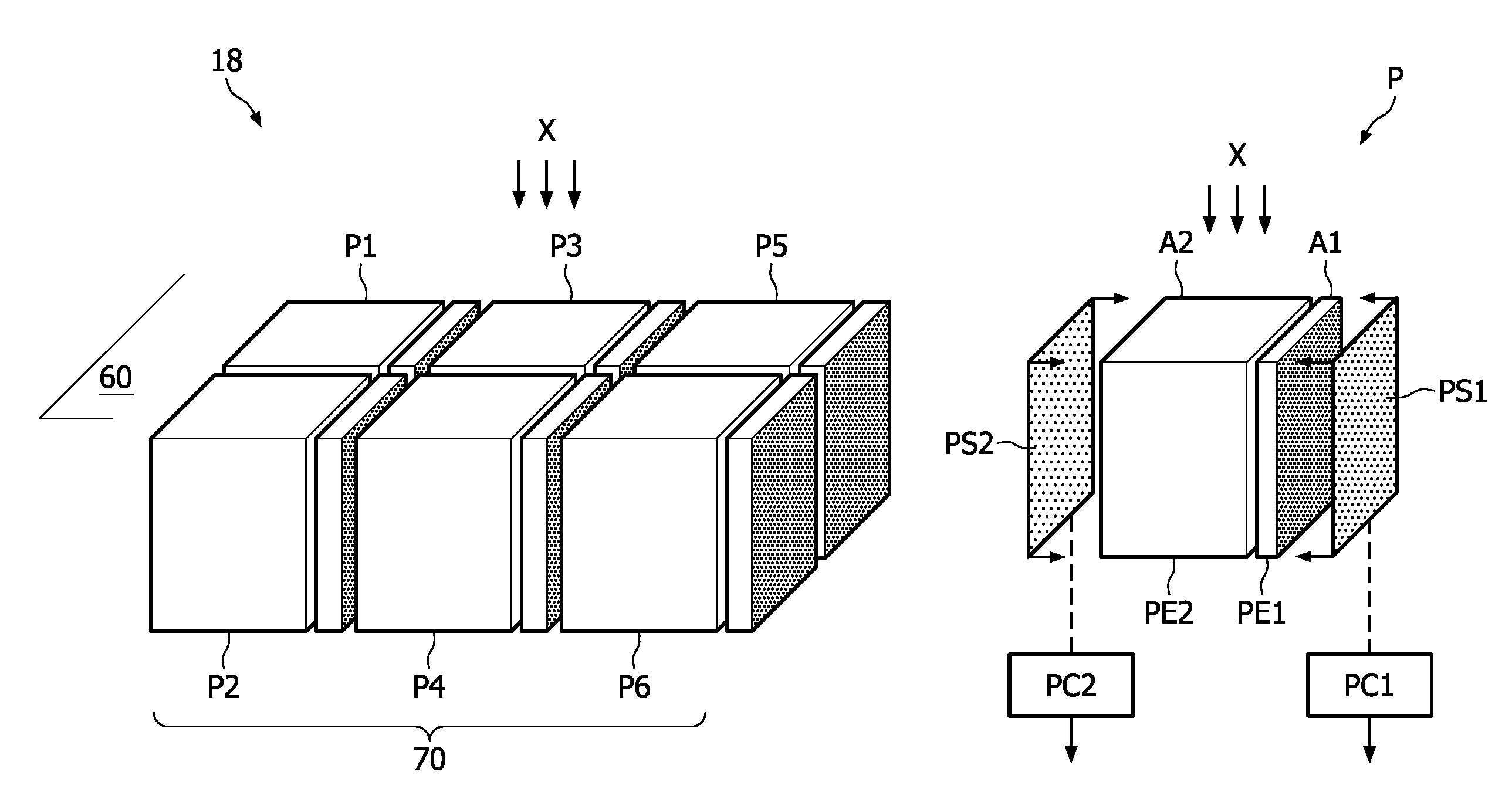
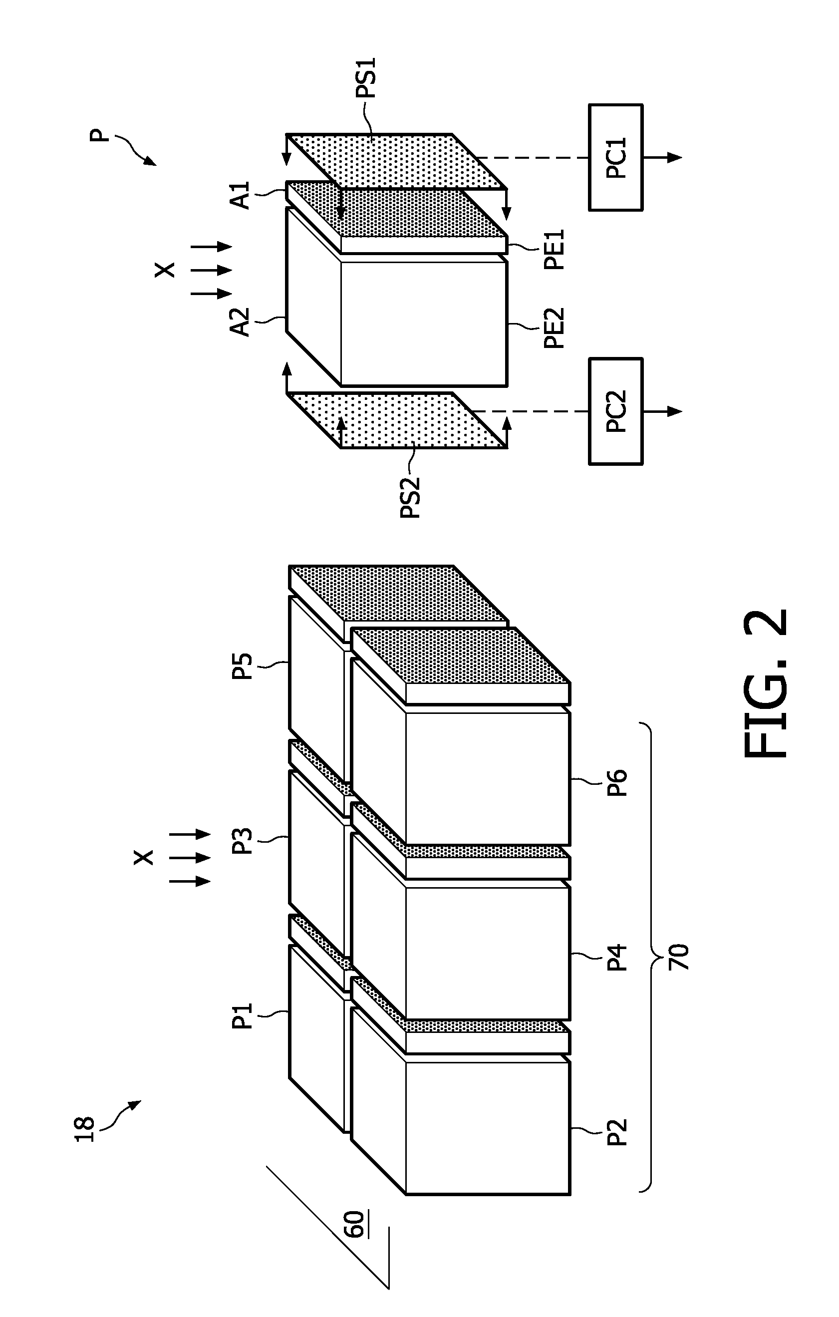
[0014]In particular, the present invention may also provide a similar spectral response from the first and the second sub-pixel, which can facilitate easier image reconstruction. Furthermore, the present invention is relatively easy to implement by using existing detector structuring technologies.
[0018]Alternatively, the second sub-pixel may have a photosensitive device arranged on a side of the sub-pixel, said side being substantially parallel to the surface plane of the array of pixels. The photosensitive device may thus be on top or at the bottom of the second sub-pixel. Both positions may be easier to manufacture. The side, which is preferably substantially orthogonal to the incoming direction of the radiation, may be positioned on a rear side, i.e. a bottom side of the detector relative to the incoming radiation.
[0019]In one embodiment, the first and the second sub-pixel may have different geometrical centers orthogonal to the surface plane of the array of pixels. The pixels can thus be next to each other, making manufacture relatively easy by separating the pixel into smaller elements. In this embodiment, the first and the second sub-pixel may have a substantially rectangular cross-sectional area parallel to a surface plane of the array of pixels. Such box-shaped configurations of the sub-pixels can thus be made conveniently. For the rectangular configuration, the side with the photosensitive device arranged thereon is preferably the side of the first sub-pixel with the largest area so as to ensure maximum optical coupling between the sub-pixel and the corresponding photosensitive device.
[0020]In another embodiment, the first and the second sub-pixel may have substantially the same geometrical center orthogonal to the surface plane of the array of pixels, thereby providing a high degree of symmetry that may be beneficial for rebinning, though it may be more difficult to manufacture the detector with this symmetry.
[0024]In one embodiment, the first and the second sub-pixel may be connected to photon-counting circuitry means so as to apply the invention in connection with high counting rates i.e. higher than 1 Gcps. Specifically, the first and the second sub-pixel may be arranged with the photon-counting circuitry means so as to measure two different sub-ranges of flux density radiation The lowest sub-range is detected by the largest sub-pixel or alternatively by the combination of the two sub-pixels. In the highest sub-range, the photon detection is done only by the sub-pixel with the smallest area. The counted photon numbers in the different sub-pixels can be easily corrected to represent the true radiation flux density which is required for image reconstruction. Correspondingly, three or more sub-pixels may be combined into various detection sub-ranges.

Problems solved by technology

The beam traverses through the object, thereby causing an attenuation of the intensity of the X-ray beam.
One of the general disadvantages of photon-counting detectors as compared to standard CT detectors which are based on current integration techniques is the relatively low X-ray flux density that can be measured without getting large errors or signal saturation.
However, the detection of random photons with temporal Poisson distribution makes it very difficult to reach the required maximal count rates for efficient imaging.
A clear drawback of this approach is the great increase in the number of individual electronic channels that should be routed and processed.
In addition, in some detector types (mainly pixelated scintillators), the structuring of small sub-pixels may introduce technical problems and reduce the effective detection area.
This technique may also introduce significant complications with respect to photon-counting spectral analysis, because the spectral response of each layer is different than the others.
In this case, complicated calibrations and corrections may be required.

Method used


Image

  • Indirect radiation detector
  • Indirect radiation detector
  • Indirect radiation detector

Examples


Embodiment Construction

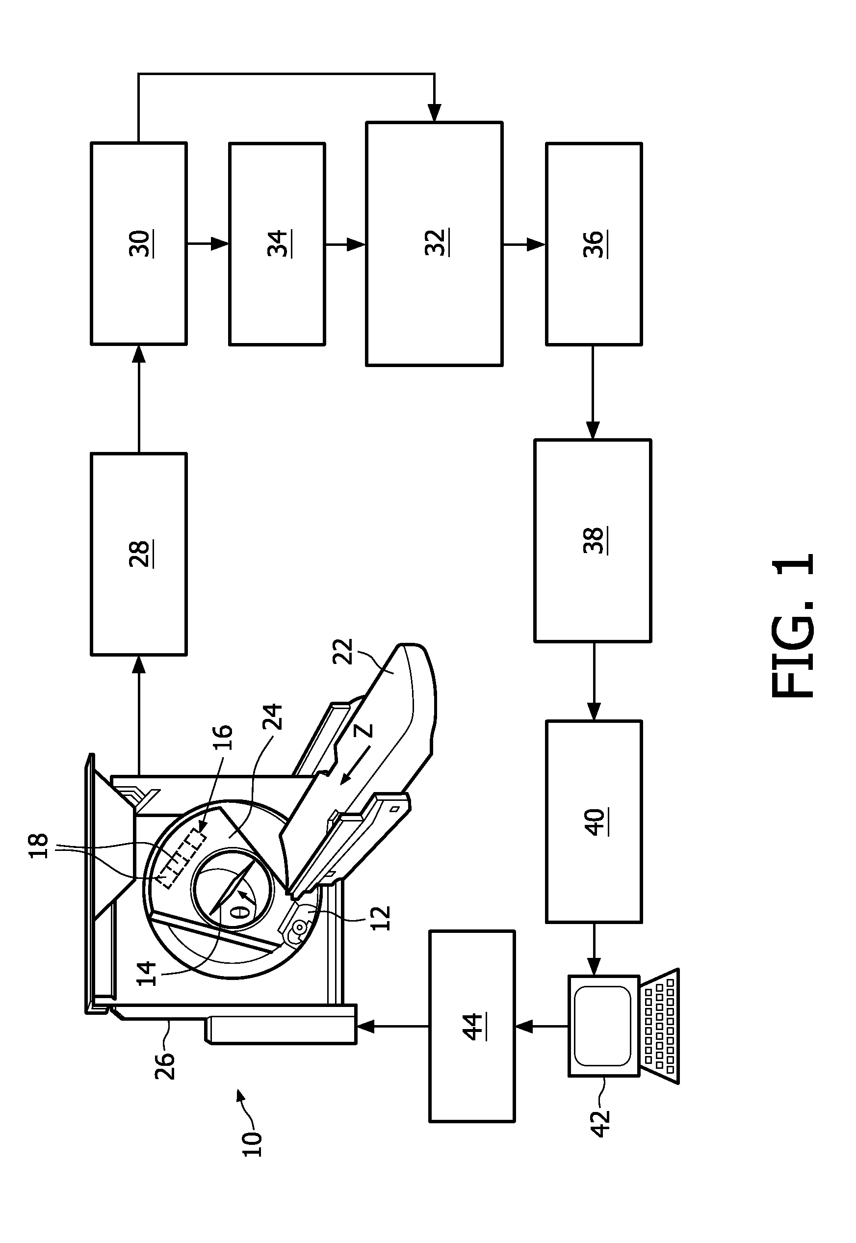
[0039]FIG. 1 is a schematic representation of a computed tomography (CT) imaging system, in which a computed tomography scanner 10 houses or supports a radiation source 12, which in one embodiment is an X-ray source, projecting a radiation beam into an examination area 14 defined by the scanner 10. After passing through the examination area 14, the radiation beam is detected by a two-dimensional radiation detector 16 arranged to detect the radiation beam after passing through the examination area 14. The radiation detector 16 includes a plurality of detection modules or detection elements 18. Typically, the X-ray tube produces a diverging X-ray beam having a cone beam, wedge beam, or other beam geometry that expands as it passes through the examination area 14 to substantially fill the area of the radiation detector 16.

[0040]An imaging subject is placed on a couch 22 or other support that moves the imaging subject into the examination area 14. The couch 22 is linearly movable along ...


PUM


Abstract

The present invention relates to an indirect radiation detector for detecting radiation (X), e.g. for medical imaging systems. The detector has an array of pixels (P1-P6), each pixel (P) being sub-divided into at least a first and a second sub-pixel (PE1, PE2). Each sub-pixel has a cross-sectional area (A1, A2) parallel to a surface plane (60) of the array. The cross-sectional area (A1) of the first sub-pixel (PE1) is different, e.g. smaller, from the cross-sectional area (A2) of the second sub-pixel (PE2) to provide a dynamic range of detectable flux densities. Additionally, the first sub-pixel (PE1) has a photosensitive device (PS1) arranged on a side of the sub-pixel, said side being substantially orthogonal to said surface plane of the array of pixels to provide a good optical coupling. The detector allows high-flux photon counting with a relatively simple detector design.

Description

FIELD OF THE INVENTION[0001]The present invention relates to an indirect radiation detector for detecting radiation, in particular X-ray radiation applied for medical imaging purposes. The invention also relates to a corresponding method of detecting radiation, and a corresponding computer program product.BACKGROUND OF THE INVENTION[0002]In typical radiographic imaging systems, e.g. X-ray imaging systems and computed tomography (CT) systems, an X-ray source or emitter radiates X-rays towards an object, e.g. a patient or other objects. The beam traverses through the object, thereby causing an attenuation of the intensity of the X-ray beam. The reduced intensity of the beam can be measured by radiation detectors if appropriately located with respect to the X-ray source and the object being examined.[0003]In other radiographic imaging systems, e.g. positron emission tomography (PET) or single photon emission computed tomography (SPECT), a radiation source is inserted into the object, a...

Claims


Application Information

Patent Timeline
IPC IPC(8): G01T1/166G01T1/20A61B6/03
CPCG01T1/2928
Inventor CARMI, RAZALTMAN, AMI
Owner KONINKLIJKE PHILIPS ELECTRONICS NV
Learn More