Miniature celestial direction detection system

Active Publication Date: 2010-11-11
TREX ENTERPRISES CORP
View PDF7 Cites 40 Cited by
  • Summary
  • Abstract
  • Description
  • Claims
  • Application Information

AI Technical Summary

Benefits of technology

[0021]To prove the advantages of the present invention Applicants have actually built and successfully tested a two-camera prototype unit. This unit has been combined with an off-the-shelf military binocular unit (the Victor 21 stabilized binoculars) designed for use with a magnetic compass and a range finder for target localization. The binoculars include a line of sight stabilization feature to eliminate movement and jitter of the laser beam.
[0022]This embodiment basically supplements the magnetic compass to provide a much more accurate target designator. The prototype unit reduces the target localization error from about 10 to 17 milliradians (which corresponds to an error of 50 to 85 meters at 5 km) down to 1 milliradian, or 5 m at 5 km range. Hardware mounted on the binoculars consists of a daytime camera with a 180 degree fisheye lens (for viewing the sun), and a separate nighttime camera (for viewing

Problems solved by technology

Magnetic compasses are typically accurate to only one degree, and the presence of steel or other local disturbances will often reduce accuracy of the magnetic compasses to several degrees or render them useless.
Therefore, if positioning of a target depends on the use of a magnetic compass, substantial position errors could likely res

Method used


Image

  • Miniature celestial direction detection system
  • Miniature celestial direction detection system
  • Miniature celestial direction detection system

Examples


Example

Single Camera System

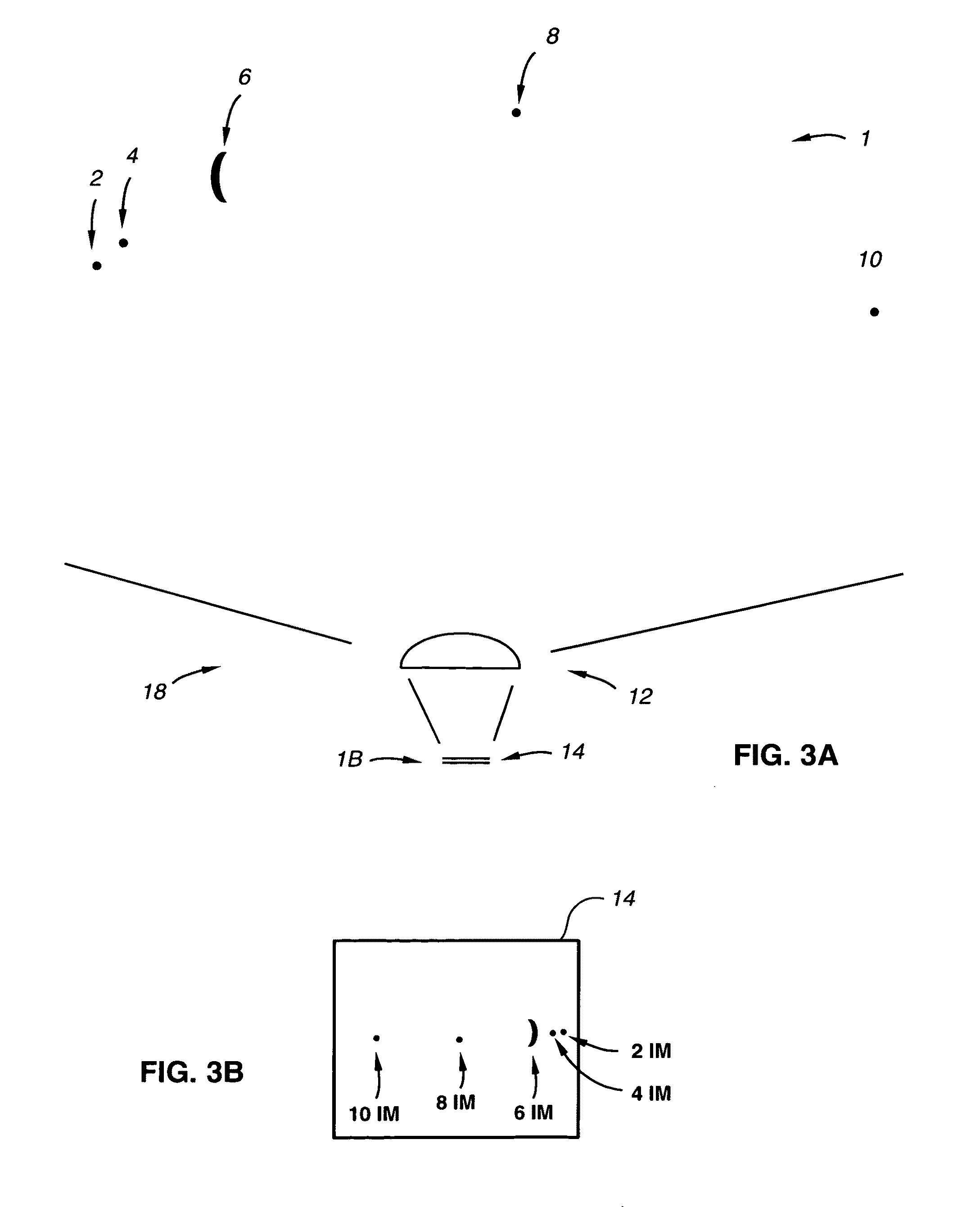
[0031]A block diagram of a prototype of the present invention actually built and tested by Applicants is shown in FIG. 3. It is a celestial compass and includes a camera 18 having a fisheye lens 12 suitable for viewing almost an entire hemisphere of the sky and a 1.3-million pixel sensor 14 for collecting images of celestial objects such as stars, planets, the moon and the sun. The celestial compass also includes a computer 22 programmed with an astronomical algorithm for providing the precise position of celestial objects based on precise input of time (date and time of day, 26) and observation position (latitude and longitude, 28), celestial navigation software 30 and coordinate transformation software 32 for converting pixel image data into astronomical coordinates, and providing a true north reference.

The Camera

[0032]As shown in FIG. 3A about 170 degrees of a nighttime hemisphere 1 is viewed via a camera 18 with a fisheye lens 12 and a 1.3-million pixel senso...


PUM


Abstract

A celestial direction finding system. The system includes an inclinometer, at least one camera for imaging both the daytime sky and the nighttime sky and a computer programmed with a sun, moon and star catalog and algorithms for automatically determining directions based on positions of celestial bodies imaged by at least one camera and incline positions measured by the inclinometer. In a preferred embodiment all of the above features are combined in a single battery operated miniature celestial direction finding module. Geographical positions of nearby objects can be determined with the addition of a rangefinder and knowledge of the geographical position of the camera. The geographical position of the system in preferred embodiments can be determined with the addition of a GPS unit.

Description

CROSS REFERENCE TO RELATED APPLICATIONS[0001]This application claims the benefit of patent application Ser. No. 11 / 604,133, Celestial Compass, filed Nov. 24, 2006 and Ser. No. 12 / 283,785, Portable Celestial Compass filed Sep. 15, 2008.FEDERAL SUPPORTED RESEARCH[0002]The present invention was made in the course of work under contract number N00178-08-C-0019 with the United States Navy and the United States Government had rights in the invention.FIELD OF INVENTION[0003]The present invention relates to direction detection systems, especially to such systems designed for use in determination of precise locations of targets.BACKGROUND OF THE INVENTIONTheodolites[0004]A theodolite is and instrument for measuring both horizontal and vertical angles. In modern theodolites, the reading out of the horizontal and vertical circles is usually done electronically. The readout is done by a rotary encoder, which can be absolute, e.g. using Gray codes, or incremental, using equidistant light and dar...

Claims


Application Information

Patent Timeline
IPC IPC(8): H04N7/18G01S19/42G01C3/04
CPCG01C21/02H04N7/18G01S19/14G01S3/7867
Inventor BELENKII, MIKHAILBRUNS, DONALDBRINKLEY, TIMOTHY
Owner TREX ENTERPRISES CORP
Why Eureka
Try Eureka