Systems and Methods for Cascaded Raman Lasing at High Power Levels

Active Publication Date: 2010-11-11
OFS FITEL LLC
View PDF15 Cites 14 Cited by
  • Summary
  • Abstract
  • Description
  • Claims
  • Application Information

AI Technical Summary

Benefits of technology

[0015]These and other issues of the prior art are addressed by the present invention, one aspect of which is directed to a light amplification system, in which a fiber-based oscillator, amplifier, and cascaded Raman resonator (CRR) are coupled together in series. The oscillator output is provided as an input into the amplifier, the amplifier output is provided as a pumping input into the CRR, and the CRR

Problems solved by technology

For example, one issue arises due to the fact that multiple reflectors at various wavelengths and positions in the system 20 combine to create coupled cavities.
In general this does not pose a problem for relatively low power systems (e.g., 5 W output at 1480 nm), but does pose a problem for high power systems.
While high power has been demonstrated from such a system, the coupled cavity nature of the setup in FIG. 1 has serious i

Method used


Image

  • Systems and Methods for Cascaded Raman Lasing at High Power Levels
  • Systems and Methods for Cascaded Raman Lasing at High Power Levels
  • Systems and Methods for Cascaded Raman Lasing at High Power Levels

Examples


Embodiment Construction

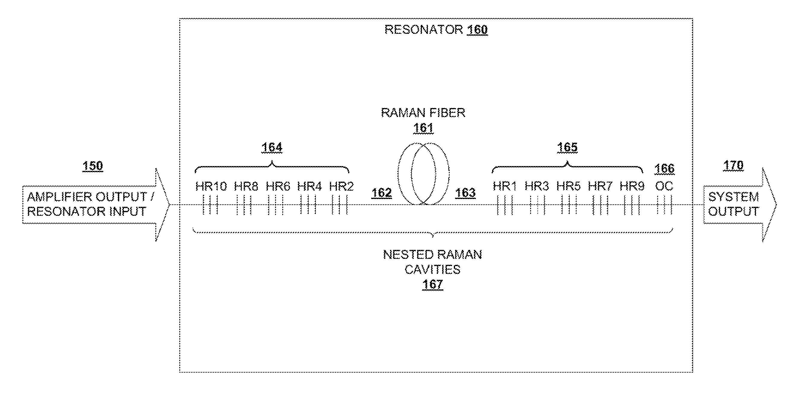
[0023]Aspects of the present invention are directed to an optical amplifier system that provides a solution to the above-described shortcomings of the prior art.

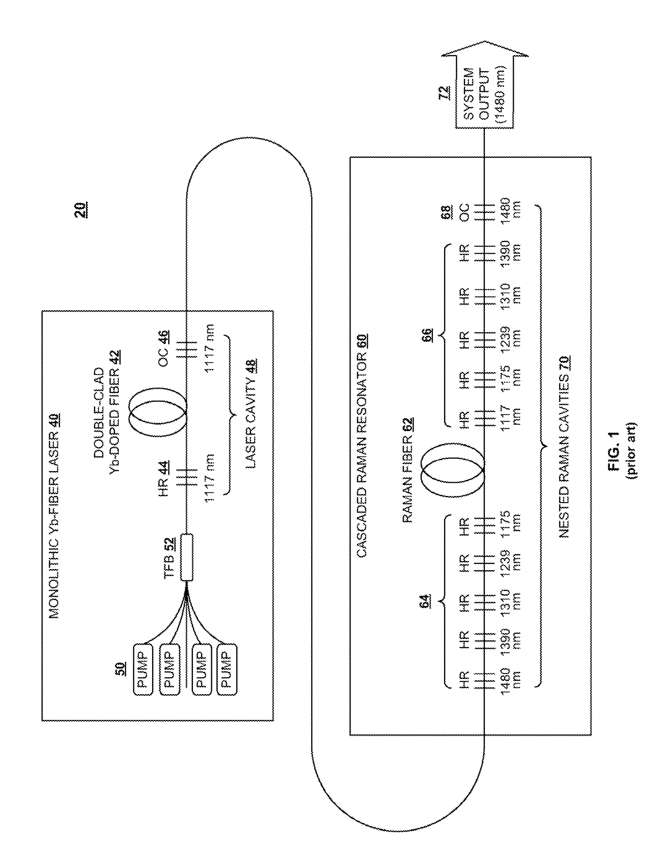
[0024]Returning to the FIG. 1 system 20, it may appear that one possible solution would be to place an optical isolator between the Yb fiber laser 40 and the CRR 60. In the FIG. 1 architecture, the high powers being investigated pose significant challenges, as 41 W of output power at 1480 nm from the CRR 60 requires greater than 100 W of input power at 1117 nm, which is far higher than current fiber coupled isolators are capable of withstanding.

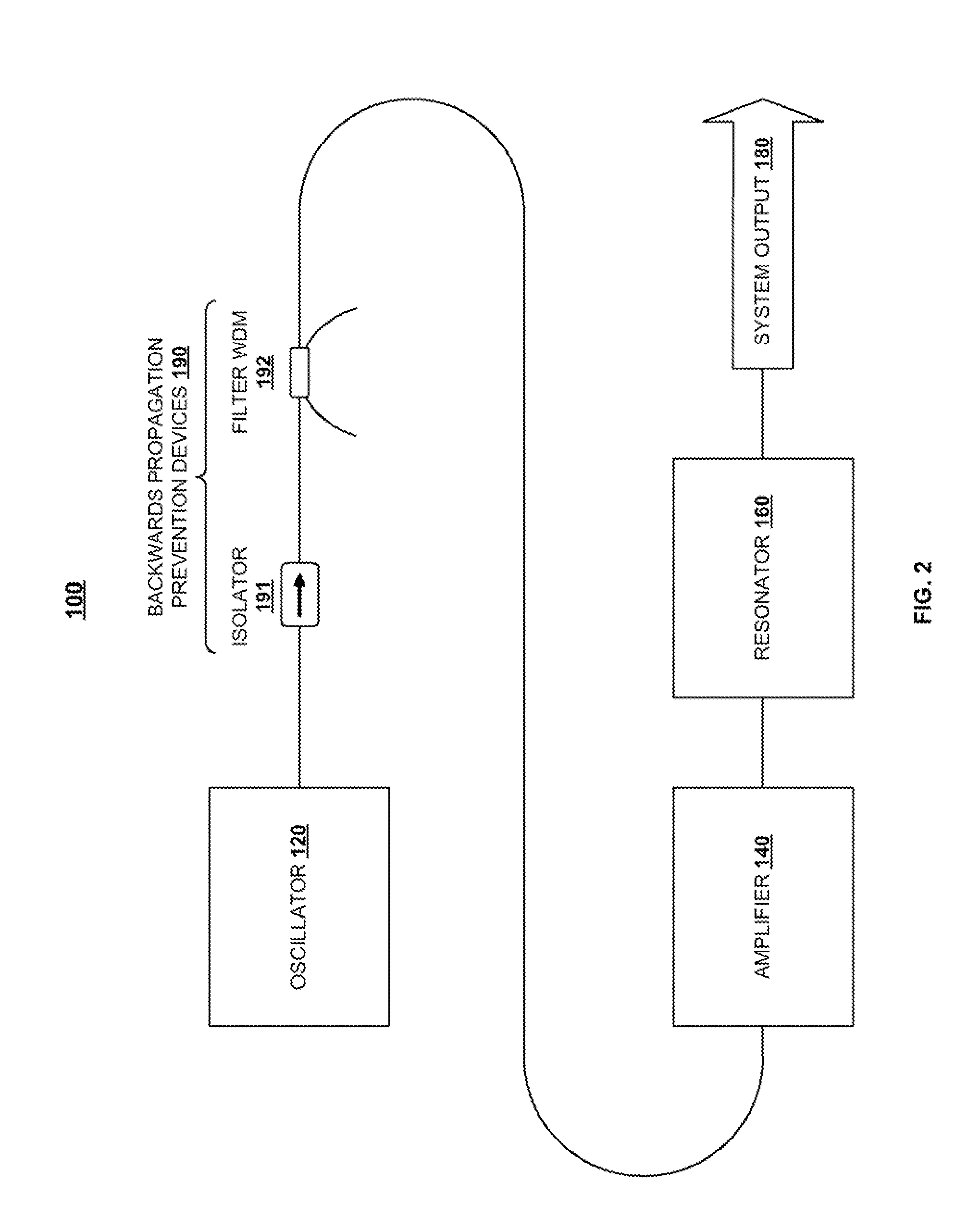
[0025]An aspect of the invention provides a solution for developing a high-power Raman laser with high reliability, in which the Yb-fiber laser, and in particular the laser's high reflector, are isolated from the Raman laser. According to this aspect of the invention, isolation is accomplished by breaking up the monolithic, high-power Yb-fiber laser into a master oscillator power ampl...


PUM


Abstract

In a light amplification system, a fiber-based oscillator, amplifier, and cascaded Raman resonator are coupled together in series. The oscillator output is provided as an input into the amplifier, the amplifier output is provided as a pumping input into the cascaded Raman resonator, and the cascaded Raman resonator provides as an output single-mode radiation at a target wavelength. A loss element is connected between the oscillator and amplifier, whereby the oscillator is optically isolated from the amplifier and cascaded Raman resonator. A filter is coupled between the isolator and the amplifier for filtering out backward-propagating Stokes wavelengths generated in the cascaded Raman resonator. The oscillator is operable within a first power level range, and the amplifier and cascaded Raman resonator are operable within a second power level range exceeding the first power level range.

Description

CROSS REFERENCE TO RELATED APPLICATION[0001]The present application claims the priority benefit of U.S. Provisional Patent Application Ser. No. 61 / 177,058, filed on May 11, 2009, which is owned by the assignee of the present application, and which is incorporated herein by reference in its entirety.BACKGROUND OF THE INVENTION[0002]1. Field of the Invention[0003]The present invention relates generally to optical fiber devices and methods, and in particular to improved systems and methods for cascaded Raman lasing at high power levels.[0004]2. Background Art[0005]Fiber lasers and amplifiers are typically based on optical fibers that are doped with laser-active rare earth ions, such as ytterbium (Yb), erbium (Er), neodymium (Nd), and the like. Stimulated Raman scattering in optical fibers is a useful effect that can be employed in order to provide nonlinear gain at wavelength regions in which these fibers do not operate. Stimulated Raman scattering occurs when a laser beam propagates t...

Claims


Application Information

Patent Timeline
IPC IPC(8): H01S3/091H01S3/30
CPCH01S3/0064H01S3/2375H01S3/0675H01S3/06754H01S3/06758H01S3/07H01S3/08086H01S3/094007H01S3/094042H01S3/09408H01S3/094084H01S3/09415H01S3/1618H01S3/302H01S3/06708H01S3/06733H01S3/094046H01S3/1608H01S3/0078
Inventor NICHOLSON, JEFFREY W.
Owner OFS FITEL LLC
Why Eureka
Try Eureka