Optical fiber, optical transmission line, optical module, and optical transmission system

Inactive Publication Date: 2010-11-11
SUMITOMO ELECTRIC IND LTD
View PDF9 Cites 2 Cited by
  • Summary
  • Abstract
  • Description
  • Claims
  • Application Information

AI Technical Summary

Benefits of technology

[0021]An optical transmission line according to the present invention comprises a single mode fiber, and an optical fiber having the structure as described above (the optical fiber according to the present invention), and has a first structure in which these single mode fiber and optical fiber are connected in cascade. Another optical transmission line according to the present invention may be one comprising a single mode fiber, a first dispersion compensating fiber, and a second dispersion compensating fiber different from the first dispersion compensating fiber, and having a second structure in which these single mode fiber, first dispersion compensating fiber, and second dispersion compensating fiber are connected in cascade. The single mode fiber has the following characteristics at the wavelength of 1550 nm: a chromatic dispersion of 12 ps/nm/km or more but 21 ps/nm/km or less; and a dispersion slope of 0.04 ps/nm2/km or more but 0.10 ps/nm2/km or less. The first dispersion compensating fiber has the same s

Problems solved by technology

The inventors have studied the above-described prior arts in detail, and as a result, have found problems as follows.
Since it results in increasing the Raylei

Method used


Image

  • Optical fiber, optical transmission line, optical module, and optical transmission system
  • Optical fiber, optical transmission line, optical module, and optical transmission system
  • Optical fiber, optical transmission line, optical module, and optical transmission system

Examples


Embodiment Construction

[0051]In the following, embodiments of an optical fiber, an optical transmission line, an optical module, and an optical transmission system according to the present invention will be described with reference to FIGS. 1A-3B, 4, 5, 6A-7C, 8-20, and 21A-23B. In the description of the drawings identical elements will be denoted by the same reference symbols, without redundant description.

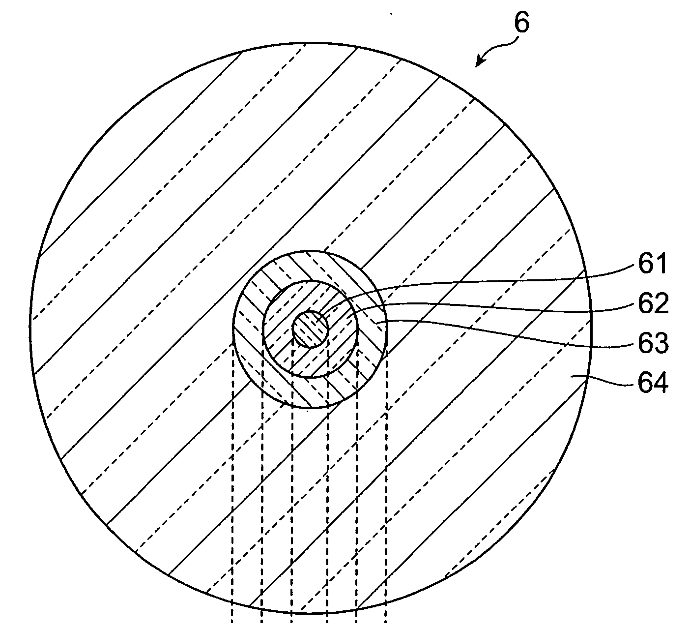
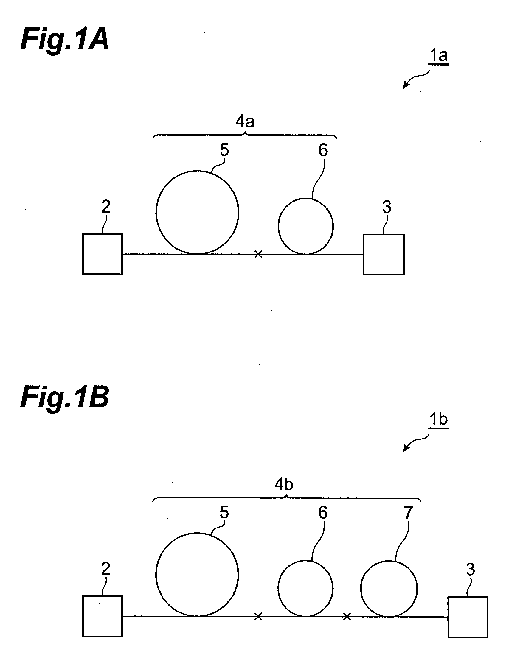
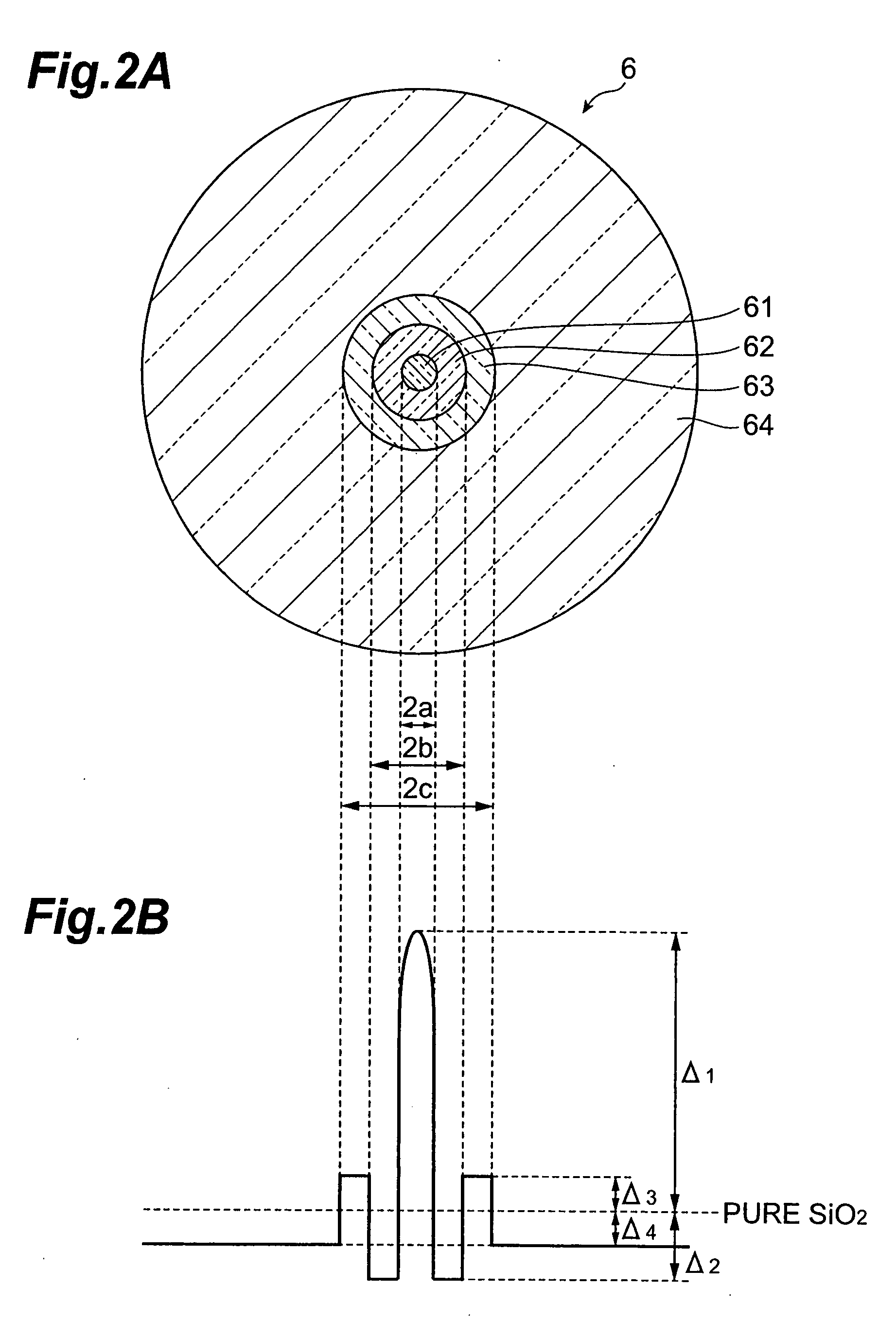
[0052]FIGS. 1A and 1B are drawings showing schematic configurations of optical transmission systems according to the present invention. The optical transmission system la shown in FIG. 1A comprises an optical transmitter 2, an optical receiver 3, and an optical transmission line 4a located between these optical transmitter 2 and optical receiver 3, and the optical transmission line 4a is constructed in a configuration in which a single mode fiber (SMF) 5 and an optical fiber 6 according to the present invention, which is prepared as a dispersion compensating fiber, are connected in cascade. The optical...


PUM


Abstract

The present invention relates to an optical fiber which has a structure for further increasing an FOM (=|dispersion|/loss) and which can be applied to a dispersion compensation module. The optical fiber is mainly composed of silica glass and has a core region including a center of an optical axis, a depressed region surrounding the core region, a ring region surrounding the depressed region, and a cladding region surrounding the ring region and doped with F. As compared with the refractive index of pure silica glass, a relative refractive index difference of the core region is greater than 2% but less than 3%, a relative refractive index difference of the depressed region is −1% or more but −0.5% or less, a relative refractive index difference of the ring region is 0.01% or more but 0.24% or less, and a relative refractive index difference of the cladding region is −0.3% or more but −0.1% or less. The FOM at the wavelength of 1550 nm is 250 ps/nm/dB or more.

Description

CROSS-REFERENCE TO RELATED APPLICATION[0001]This is a Continuation-In-Part application of the patent application Ser. No. 11 / 544,007 filed on Oct. 6, 2006 by the same Applicant, now pending.BACKGROUND OF THE INVENTION[0002]1. Field of the Invention[0003]The present invention relates to an optical transmission system for transmitting signal light through an optical fiber transmission line, and to an optical fiber and others for compensating for chromatic dispersion of the entire optical fiber transmission line.[0004]2. Related Background Art[0005]An optical transmission system uses a Single Mode Fiber (SMF) in conformity with ITU-G652.C, comprised primarily of silica glass, as an optical fiber transmission line for transmitting signal light. The C-band (1530 nm-1565 nm) is used as a wavelength band of signal light and the L-band (1565 nm-1625 nm) is also used. The SMF has the chromatic dispersion of 12 ps / nm / km or more but 21 ps / nm / km or less and the dispersion slope of 0.04 ps / nm2 / k...

Claims


Application Information

Patent Timeline
IPC IPC(8): G02B6/02
CPCC03B2203/22C03B2203/29C03B2203/36G02B6/29377G02B6/03627G02B6/03644G02B6/02261
Inventor SASAKI, TAKASHIMAKIHARA, KAZUMASAHARUNA, TETSUYAONISHI, MASASHIHIRANO, MASAAKI
Owner SUMITOMO ELECTRIC IND LTD
Why Eureka
Try Eureka