Device and process for wet treating a peripheral area of a wafer-shaped article

Inactive Publication Date: 2010-11-18
LAM RES AG
View PDF11 Cites 8 Cited by
  • Summary
  • Abstract
  • Description
  • Claims
  • Application Information

AI Technical Summary

Benefits of technology

[0016]In a preferred embodiment no rollers are arranged between the first liquid treatment unit and the second liquid treatment unit. This has the advantage that the residues of the first liquid, which has been supplied to the peripheral area, do not contact a roller. Therefore the rollers always drive the dry and clean edge of the wafer-shaped article.
[0019]With another embodiment at least one liquid carrier has the form of a groove open towards the centre of the wafer-shaped article, wherein the groove has a maximum width of 3 mm. If a wafer-shaped article is present the wafer-shaped article's edge is inserted into the groove without touching the groove's sidewalls. The groove envelopes the wafer-shaped article's edge. When liquid is supplied into the groove it is held by capillary forces without dripping off the groove. This effect is further supported when the wafer-shaped article's edge is present in the groove. Given that the wafer-shaped article has a thickness of about 0.6 mm and it is held in the centre of the groove the gaps between the sidewalls of the groove and the wafer-shaped article are about 1.2 mm at the maximum, which are small enough so that liquids of low surface tension can be held by capillary forces.
[0020]In yet another embodiment with at least one liquid treatment unit both the liquid carrier and the liquid removal section have the form of a groove open towards the centre, wherein the width of the groove of the liquid carrier is smaller than the width of the groove of the liquid removal section by at least 1 mm. This leads to the advantageous effect that liquid, which is held by capillary forces in the liquid carrier is not held by the liquid removal section. Liquid is thus retained in the liquid carrier when the wafer-shaped article's edge moves towards the liquid removal section. In other words the capillary breaks when the edge leaves the liquid carrier and most of the liquid remains in the liquid carrier's groove.
[0023]Advantageously at least one liquid treatment unit is mounted to the drive unit so that the liquid treatment unit is movable to and from the edge of the wafer-shaped article together with the roller unit. This helps to adjust the liquid treatment unit with respect to the edge almost independently of the diameter of the wafer-shaped article.

Problems solved by technology

Furthermore such compositions may harm the apparatus.

Method used


Image

  • Device and process for wet treating a peripheral area of a wafer-shaped article
  • Device and process for wet treating a peripheral area of a wafer-shaped article
  • Device and process for wet treating a peripheral area of a wafer-shaped article

Examples


example 1

A Process for Removing a Silicon Oxide Layer from the Edge with Diluted Hydrogen Fluoride (dHF)

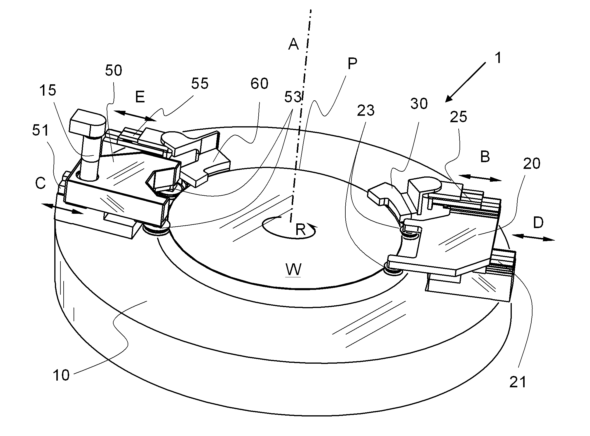
[0080]A wafer is loaded from above (with an edge-contact-only gripper such as described e.g. in U.S. Pat. No. 5,762,391) between the roller unit 20 and the drive unit 50. The roller unit 20 and the drive unit 50 are moved towards each other so that their rollers grip the wafer. After loading the wafer is turned with a spin speed of 5 rpm.

[0081]The liquid carrier of the first liquid treatment unit 30 is filled with dHF at 25° C. The liquid (dHF) in the first liquid carrier is renewed at a flow of 5 ml / min.

[0082]When the wafer W is rotated the second liquid treatment unit 60, which is filled with deionised water at 25° C., is moved towards the wafer's edge. Simultaneously or immediately thereafter the first liquid treatment 30 unit is moved to the edge of the wafer. The liquid (deionised water) in the second liquid carrier is renewed at a flow of 10 ml / min.

[0083]The drying inert gas (in this...

example 2

Process for Edge Polymer Removal

[0085]The process is carried out basically in the same way as in example 1 with the following deviations.

[0086]The liquid used in the first liquid treatment unit is a mixture of sulphuric acid and hydrogen peroxide.

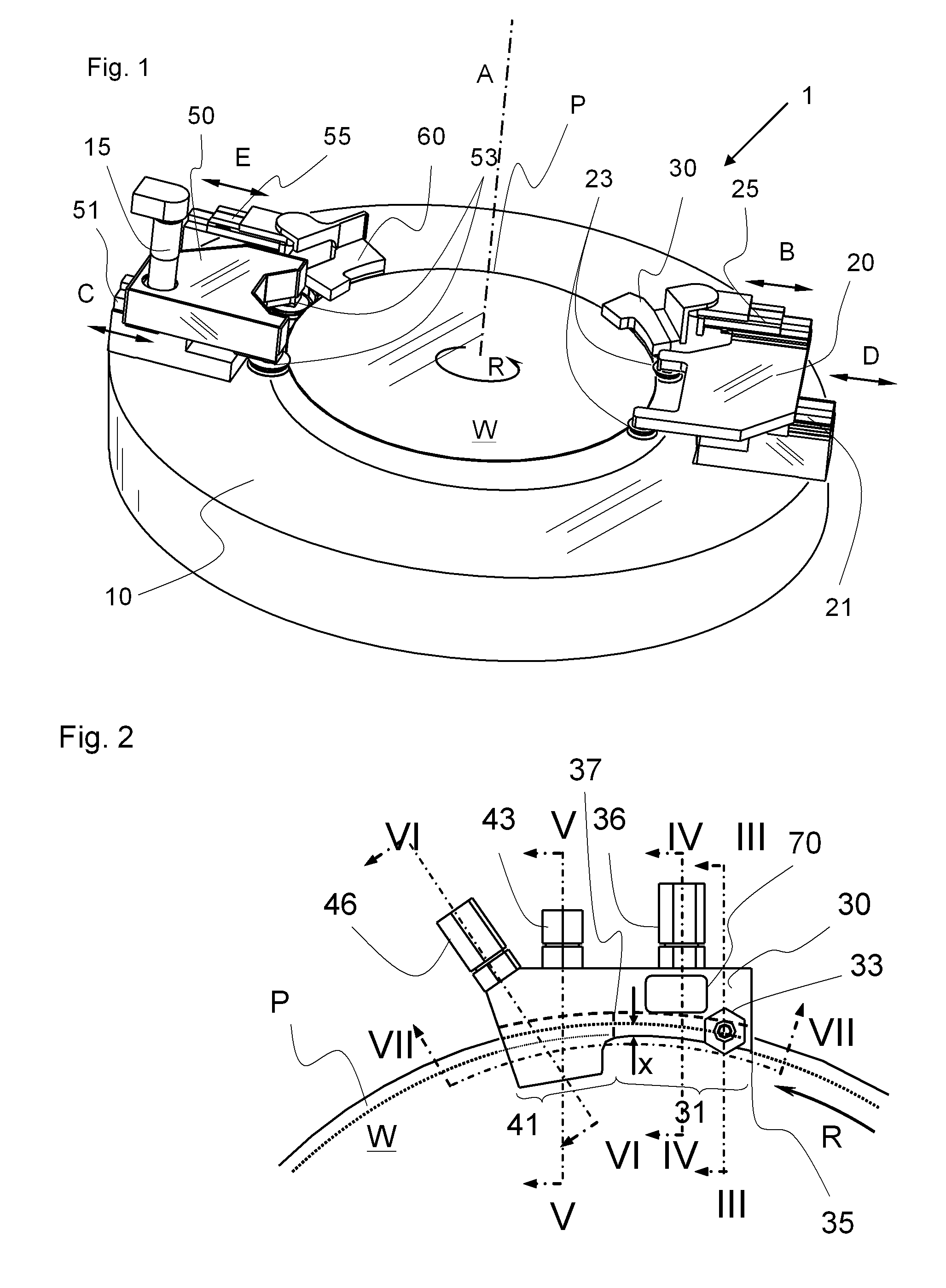
[0087]Ultrasonic agitation is applied to the edge through transducers 70 at 300 kHz.

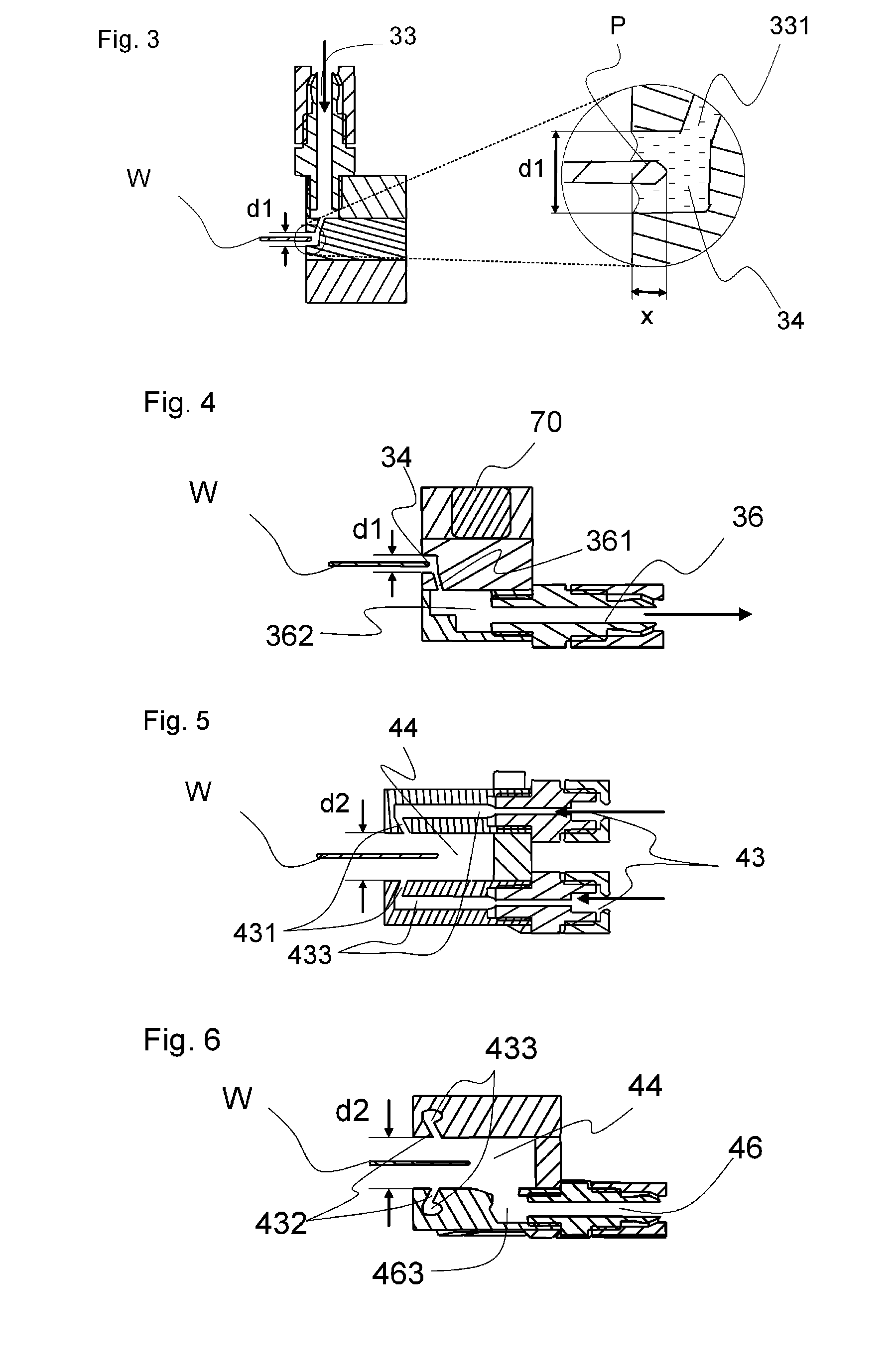
[0088]The groove of the liquid carrier is formed such that the upper side of the wafer is treated at a peripheral area of 1 mm (X=1 mm) and the lower side is treated at a peripheral area of 3 mm (X=3 mm). Therefore the liquid carrier has the shape of an asymmetric groove with sidewalls of different height or rather depth (e.g. the upper side wall has a depth of 1.5 mm whereas the lower side wall has a depth of 3.5 mm).

[0089]The liquid used in the first liquid treatment unit is supplied at a temperature of 55° C.

[0090]The second liquid treatment unit has a second liquid carrier of about the same shape as the first liquid carrier, however reaching slightly mor...


PUM


Abstract

A device for wet treating a peripheral area of a wafer-shaped article includes holding elements for holding and rotating the wafer-shaped article at its edge, a first and a second liquid treatment units for supplying liquid towards the peripheral area. The holding elements include rollers for driving the wafer-shaped article at its edge. The first liquid treatment unit includes a first liquid carrier for providing a first liquid to wet a first section of the peripheral area, a first liquid supply nozzle for supplying liquid to the first liquid carrier, and a first liquid discharging channel for removing liquid from the first liquid carrier. The second liquid treatment unit includes, a second liquid carrier for providing a second liquid to wet a second section of the peripheral area, a second liquid supply nozzle for supplying liquid to the second liquid carrier, a second liquid discharging channel for removing liquid from the second liquid carrier, and a second gas treatment section with a gas supply nozzle for supplying gas towards the peripheral area, which has been treated with the second liquid for removing most of the second liquid from the peripheral area, and with a gas discharge channel for discharging gas and removed liquid.

Description

TECHNICAL FIELD[0001]The invention relates to a device and process for wet treating a peripheral area of a wafer-shaped articleBACKGROUND ART[0002]U.S. Pat. No. 6,435,200 discloses an apparatus for etching a peripheral region of the disc-like article. The liquid is supplied to the surface of the disc-like article which does not face the chuck and is held in a gap between the disc-like article and a ring.[0003]For specific application a mechanical force is advantageous in order to properly treat the peripheral region, e.g. in order to remove a specific layer from the peripheral region. Sometimes very aggressive compositions must be used for properly removing a specific layer. Furthermore such compositions may harm the apparatus.[0004]WO2003 / 023825A2 discloses an apparatus for etching a peripheral region of a wafer-shaped article. Liquid is supplied at a single point and is removed immediately thereafter. Only one liquid can be supplied at one time. If the liquid is not properly remov...

Claims


Application Information

Patent Timeline
IPC IPC(8): B08B3/00
CPCH01L21/6708H01L21/67051
Inventor FRANK, DIETERPARZEFALL, JURGENSCHWARZFURTNER, ALEXANDER
Owner LAM RES AG
Why Eureka
Try Eureka