
Fuel injection valve

a fuel injection valve and electromagnet technology, applied in the direction of fuel injection apparatus, spraying apparatus, charge feed system, etc., can solve the problems of deterioration of exhaust gas and engine controllability, and increase of so as to achieve a large pressure loss, increase in fuel adhesion to various parts of the engine, and deterioration of flow rate dynamic rang

Active Publication Date: 2010-11-18
MITSUBISHI ELECTRIC CORP
View PDF7 Cites 32 Cited by
  • Summary
  • Abstract
  • Description
  • Claims
  • Application Information

AI Technical Summary

Benefits of technology

[0007]In the foregoing prior arts, because the fluid resistance is large at the downstream side of a valve seat, the pressure reducing speed is low at the downstream side of the valve seat during the valve body closing process; therefore, because the valve closing delay time in which a valve closing signal is input and then the valve body is completely closed is long, the flow rate dynamic range is deteriorated.
[0008]Because the fluid resistance is large at the downstream side of the valve seat, the fuel spray injected through the injection hole is liable to adhere; therefore, there may be caused a splashing phenomenon in which the fuel that has not been able to separate from the injection hole and has adhered to the endface, of the injection hole plate, in the vicinity of the injection hole outlet is splashed when the next injection is performed, whereby inferior fuel spray is injected outside the target injection zone; as a result, fuel adhesion to various parts of the engine increases, whereby exhaust gas and the controllability in the engine output may be deteriorated.
[0009]Under a high-temperature and negative-pressure condition, due to vaporization of part of fuel in a so-called dead volume, a gas-liquid two-layer flow is caused, and the pressure loss is large when the gas-liquid two-layer flow passes through a narrow flow path; in the example of prior art, because the flow path is configured in such a way that the guide path, i.e., a diaphragm is provide from the downstream side of the valve seat to the injection hole, there has been a problem that, due to change in the temperature or the atmospheric pressure, the flow rate characteristics (static flow rate/dynamic flow rate) and the fuel spray characteristics (fuel spray shape/fuel-spray particle diameter) change consid

Problems solved by technology

Meanwhile, in the prior arts disclosed in Japanese Patent Application Laid-Open No. 2003-336562 and Japanese Patent Application Laid-Open No. 2003-336563, a fuel injection valve is configured in such a way that respective guide paths are provided for the injection holes, and a fuel rectified and accelerated by means of the guide path flows into a swirl chamber; therefore, there have been such problems as described below.
In the foregoing prior arts, because the fluid resistance is large at the downstream side of a valve seat, the pressure reducing speed is low at the downstream side of the valve seat during the valve body closing process; therefore, because the valve closing delay time in which a valve closing signal is input and then the valve body is completely closed is long, the flow rate dynamic range is deteriorated.
Because the fluid resistance is large at the downstream side of the valve seat, the fuel spray injected through the injection hole is liable to adhere; therefore, there may be caused a splashing phenomenon in which the fuel that has not been able to separate from the injection hole and has adhered to the endface, of the injection hole plate, in the vicinity of the injection hole outlet is splashed when the next injection is performed, whereby inferior fuel spray is injected outside the target injection zone; as a result, fuel adhesion to various parts of the engine increases, whereby exhaust gas and the controllability in the engine output may be deteriorated.
Under a high-temperature and negative-pressure condition, due to vaporization of part of fuel in a so-called dead volume, a gas-liquid two-layer flow is caused, and the pressure loss is large when the gas-liquid two-layer flow passes through a narrow flow path; in the example of prior art, because the flow path is configured in such a way that the guide path, i.e., a diaphragm is provide from the downstream side of the valve seat to the injection hole, there has been a problem that, due to change in the temperature or the atmospheric pressure, the flow rate characteristics (static flow rate / dynamic flow rate) and the fuel spray characteristics (fuel spray shape / fuel-spray particle diameter) change considerably.
Because the speed of the fuel that flows into each swirl chamber depends on the shape of the guide path, the variation in the shape of the guide path largely affects the deviation of the injection amount of the fuel injected through the injection hole; therefore, a guide path having a high-accuracy shape is required, whereby the production cost is raised.
When the deviation of the injection amount is large, the shape of the fuel spray varies, whereby, when the fuel is injected in the engine, the adhesion amount in various part of the engine and the distribution of the fuel-air mixture vary; therefore, the variation in combustion may cause an increase in the amount of exhaust gas or a fluctuation of the engine rotation.
Accordingly, the machining of the fuel path becomes difficult, and in the case where the fuel path is formed with a press machine, there has been a problem that the lifetime of the die is shortened and hence the production cost increases.
In the case where a multi-hole injector is adopted for the purpose of further atomizing the fuel spray, the diameter of each injection hole becomes small and hence the fuel path becomes narrow, whereby the machining of the fuel path becomes difficult; therefore, in the case where the fuel path is formed with a press machine, there has been a problem that the lifetime of the die is shortened and hence the production cost increases.
In the prior arts disclosed in Japanese Patent Application Laid-Open No. 2006-2620 and Japanese Patent Application Laid-Open No. 2006-336577, a fuel injection valve is configured in such a way that the fuel flow is controlled based on the relationship between the shape of the fuel chamber and the position of the injection hole and a swirling flow is induced at the injection hole inlet; thus, there have been such problems as described below.
Because the fuel injection valve according to the foregoing prior arts has no swirl chamber and has a flow opposite to the swirling flow, there has been a problem that the swirling flow does not develop sufficiently and hence the atomization is not facilitated.
When the injected hollow liquid films spread due to centrifugal force, there exists a disturbance in the fuel flow in the case of the foregoing prior arts; therefore, the liquid film is split, with the thickness thereof kept thick, in process of spreading.
There has been a problem that, because the split liquid thread or liquid drop is not likely to further split, the fuel cannot readily be atomized.
The flow path is made in such a way that, in the fuel chamber at the upstream side of the injection hole, the fuel flow separates from the rest; therefore, there has been a problem that, due to the disturbance in the separated fuel, the flow rate characteristics and the fuel spray characteristics are likely to vary.
Under a high-temperature and negative-pressure condition, the fuel separation makes the fuel tend to boil under reduced pressure; therefore, there has been a problem that, due to atmospheric change, the flow rate characteristics (static flow rate / dynamic flow rate) and the fuel spray characteristics (fuel spray shape / fuel-spray particle diameter) change considerably.
Also in the prior art disclosed in Japanese Patent Application Laid-Open No. 2007-182767, the fuel flow is controlled based on the relationship between the shape of the fuel chamber and the position of the injection hole and a swirling flow is induced at the injection hole inlet; thus, there has been such a problem described below.
Because the fuel injection valve according to the foregoing prior art has no swirl chamber and has a flow opposite to the swirling flow, there has been a problem that the swirling flow does not develop sufficiently and hence the atomization is not facilitated.

Method used


Image

  • Fuel injection valve
  • Fuel injection valve
  • Fuel injection valve

Examples


embodiment 1

Corresponding to Claims 1 to 4

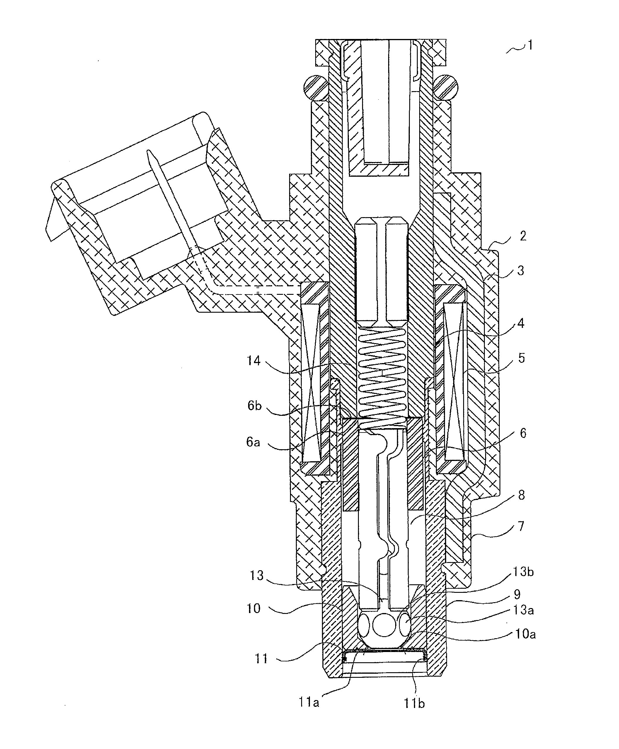
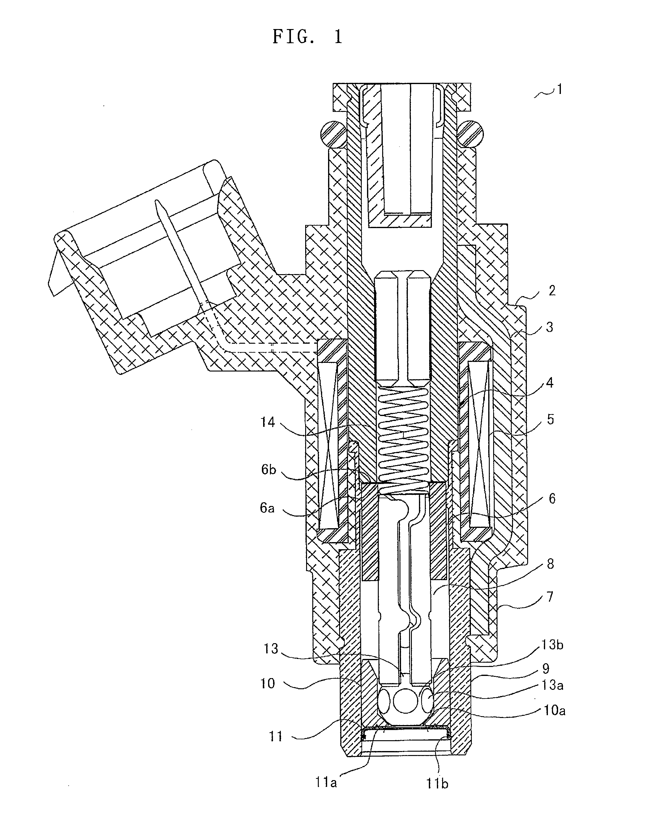
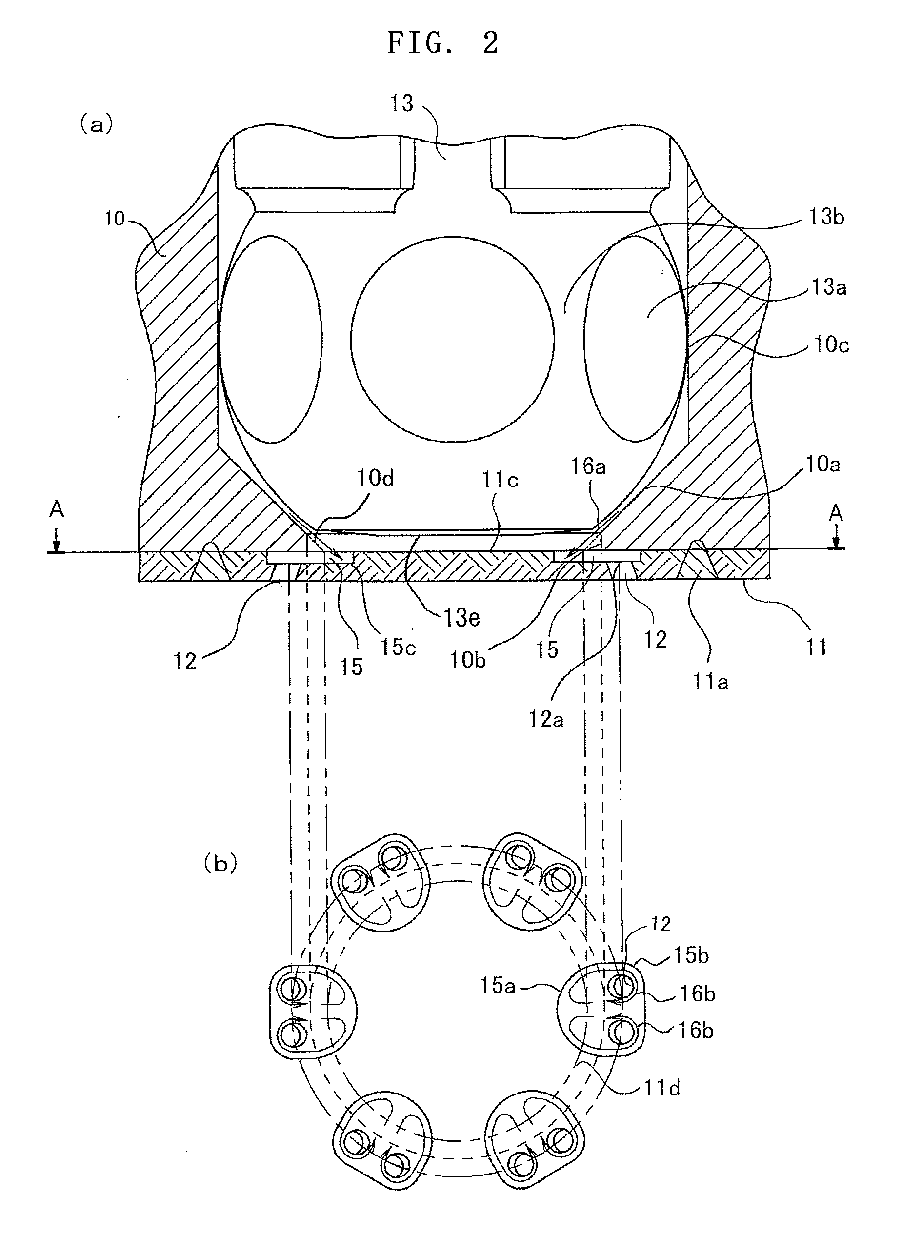
[0047]FIGS. 1 and 2 illustrate Embodiment 1 of the present invention; FIG. 1 is a cross-sectional view of a fuel injection valve; FIG. 2(a) is an enlarged cross-sectional view of the front end portion of a fuel injection valve; FIG. 2(b) is a plan view of the front end portion of a fuel injection valve in the case where the plane taken along the line A-A in FIG. 2(a) is viewed along the arrows.

[0048]A fuel injection valve 1 is provided with a solenoid device 2, a housing 3 that is a yoke portion of a magnetic circuit, a core 4 that is a fixed iron core portion of the magnetic circuit, a coil 5 wound around a bobbin provided on the circumference of the core 4, an armature 6 that is a moving iron core portion of the magnetic circuit, and a valve device 7. The valve device 7 is configured with a valve body 8, a valve main body 9, and a valve seat 10. At the front end of the valve body 8, a valve-body front end portion 13, which forms part of a sphere, is m...

embodiment 2

Corresponding to Claim 5

[0060]FIG. 3 illustrates the front end portion of a fuel injection valve according to Embodiment 2; FIG. 3(a) is a cross-sectional view of the front end portion; FIG. 3(b) is a plan view of the front end portion of a fuel injection valve in the case where the plane taken along the line B in FIG. 3(a) is viewed along the arrows. In Embodiment 2, fuel chambers 15 formed in an injection hole plate 11 are ellipsoidal; a single injection hole 12 is provided in each of the fuel chambers 15; the injection hole 12 is disposed outside the inner circumference of a valve seat opening portion 10b.

[0061]As illustrated in FIG. 3, two or more (ten, in the case of FIG. 3) fuel chambers 15 are provided in a place that ranges from the inside of a virtual circle 11d to the outside of the inner circumference of the valve seat opening portion 10b. The fuel chamber 15 is ellipsoidal; the major axis thereof is slanted by α° with respect to a radial line that extends from the cente...

embodiment 3

Corresponding to Claims 6 to 8

[0063]FIG. 4 illustrates the front end portion of a fuel injection valve according to Embodiment 3; FIG. 4(a) is a cross-sectional view of the front end portion; FIG. 4(b) is a plan view of the front end portion of a fuel injection valve in the case where the plane taken along the line C-C in FIG. 4(a) is viewed along the arrows; FIG. 4(c) is a cross-sectional view, taken along the line D-D, of the front end portion of a fuel injection valve. In Embodiment 3, the structure of a valve-body front end portion 13 and a fuel chamber 15 are different from those in Embodiment 1.

[0064]In Embodiment 3, as illustrated in FIG. 4, a plurality of grooves 13a is formed in such a way as to be spaced evenly apart from one another in a sphere-shaped peripheral portion of the valve-body front end portion 13; each of the grooves 13a is formed of a semicircle-shaped plane 13d and another plane 13c that intersects the plane 13d. The plane 13c is provided in such a way as to...


PUM


Abstract

There is obtained an internal combustion engine fuel injection valve in which, by suppressing increase in production costs, deterioration in the accuracy of a flow rate, and variations in various kinds of characteristics caused by a change in the atmospheric air pressure, the quality of atomized fuel spray is improved.An injection hole plate 11 is disposed in such a way that an extended line 10d along the plane of a valve seat portion of a valve seat whose diameter is gradually reduced in the downstream direction and an upstream plane 11c of the injection hole plate 11 intersect each other so that a virtual circle 11d is formed; by recessing part of the upstream side of the injection hole plate 11 at a plurality of positions along the valve seat opening portion 10b, a plurality of fuel chambers 15 is formed; the fuel chamber 15 is in a shape, the halves of which are symmetric with each other with respect to a line that radially extends from the center of the injection hole plate 11, and is disposed in a place that ranges from the inside of the virtual circle 11d to the outside of the inner circumference of the valve seat opening portion 10b; and in each of the fuel chambers 15, two injection holes 12 are arranged outside the inner circumference of the valve seat opening portion 10b in such a way as to flank the radial center line of the fuel chamber 15.

Description

BACKGROUND OF THE INVENTION[0001]1. Field of the Invention[0002]The present invention relates to an electromagnetic fuel injection valve utilized mainly in the fuel supply system of an internal combustion engine.[0003]2. Description of the Related Art[0004]In recent years, while restrictions on exhaust gas from a vehicle and the like have been tightened, there has been required improvement in atomization of a fuel injected through a fuel injection valve, and hence various kinds of studies about atomization have been made. In the prior arts disclosed in Japanese Patent Application Laid-Open No. 2003-336562 and Japanese Patent Application Laid-Open No. 2003-336563, a fuel injection valve is configured in such a way that respective guide paths are provided for the injection holes, and a fuel rectified and accelerated by means of the guide path flows into a swirl chamber. The fuel forms a swirling flow in the swirl chamber and swirls within the injection hole; then, a fuel spray injecte...

Claims


Application Information

Patent Timeline
IPC IPC(8): F02M51/06
CPCF02M61/162F02M61/163F02M61/1853F02M61/186F02M51/0682
Inventor HASHII, NAOYAMUNEZANE, TSUYOSHI
Owner MITSUBISHI ELECTRIC CORP
Learn More