High power uhf single-pole multi-throw switch

a switch and multi-throw technology, applied in the field of electric high frequency high power electronically controlled switches, can solve the problems of lack of commercially available high peak, lack of design flexibility, single or multi-throw switch of high average power, etc., and achieve the effect of low insertion loss and high insertion loss

Active Publication Date: 2010-11-18
LOCKHEED MARTIN CORP
View PDF17 Cites 12 Cited by
  • Summary
  • Abstract
  • Description
  • Claims
  • Application Information

AI Technical Summary

Benefits of technology

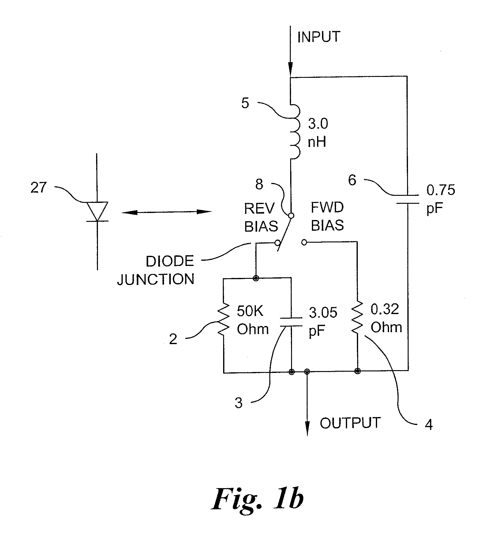
[0005]According to an aspect of the present invention, a single pole multiple-throw microwave switch for selectively switching an RF signal to one of a plurality of output ports comprising: a transmission line for coupling the signal to a single or multi-throw junction, the throw junction having connected thereto a plurality of switch legs, each said leg including a high voltage shunt diode spaced about one quarter-wavelength from the throw junction; each said diode mounted at its cathode end to a corresponding Direct Current (“DC”) blocking capacitor and adapted to receive a bias voltage; wherein a controller applies a first DC bias voltage to a selected one of the shunt diodes to cause the selected shunt diode to operate in a reverse bias mode such that the selected shunt diode mounted on the corresponding capacitor provides a low insertion loss to pass the signal from the transmission line through a selected leg and to a selected output port, and the controller applies a second DC bias voltage to the other shunt diodes to cause the other shunt diodes to operate in a forward bias mode, wherein the other shunt diodes provide a high insertion loss for blocking the signal from the transmission line to the remaining plurality of output ports.

Problems solved by technology

The prior art provides switches that are often contained in large packages and do not allow design flexibility insofar as electronic switch control.
In fact, presently there exists a lack of commercially available high peak, high average power single pole, single or multi-throw switches capable of handling 10-25 kilowatt (“kW”) for use in electronic applications generally and more particularly airborne radar / electronic warfare applications.
Furthermore, the prior art does not offer an Ultra High Frequency (“UHF”) switch in the same package as its digitally controlled circuits.
Finally, the prior art offers no acceptable product that takes into account the multiple requirements of low insertion loss, high off-arm isolation, and low-risk switch bias / control injection to support operation exceeding 10 kW operation.

Method used


Image

  • High power uhf single-pole multi-throw switch
  • High power uhf single-pole multi-throw switch
  • High power uhf single-pole multi-throw switch

Examples


Embodiment Construction

[0016]It is to be understood that the figures and descriptions of the present invention have been simplified to illustrate elements that are relevant for a clear understanding, while eliminating, for the purpose of clarity, many other elements found in switch technology and methods of making and using each of the same. Those of ordinary skill in the art may recognize that other elements and / or steps may be desirable in implementing the present invention. However, because such elements and steps are well known in the art, and because they do not facilitate a better understanding of the present invention, a discussion of such elements and steps is not provided herein.

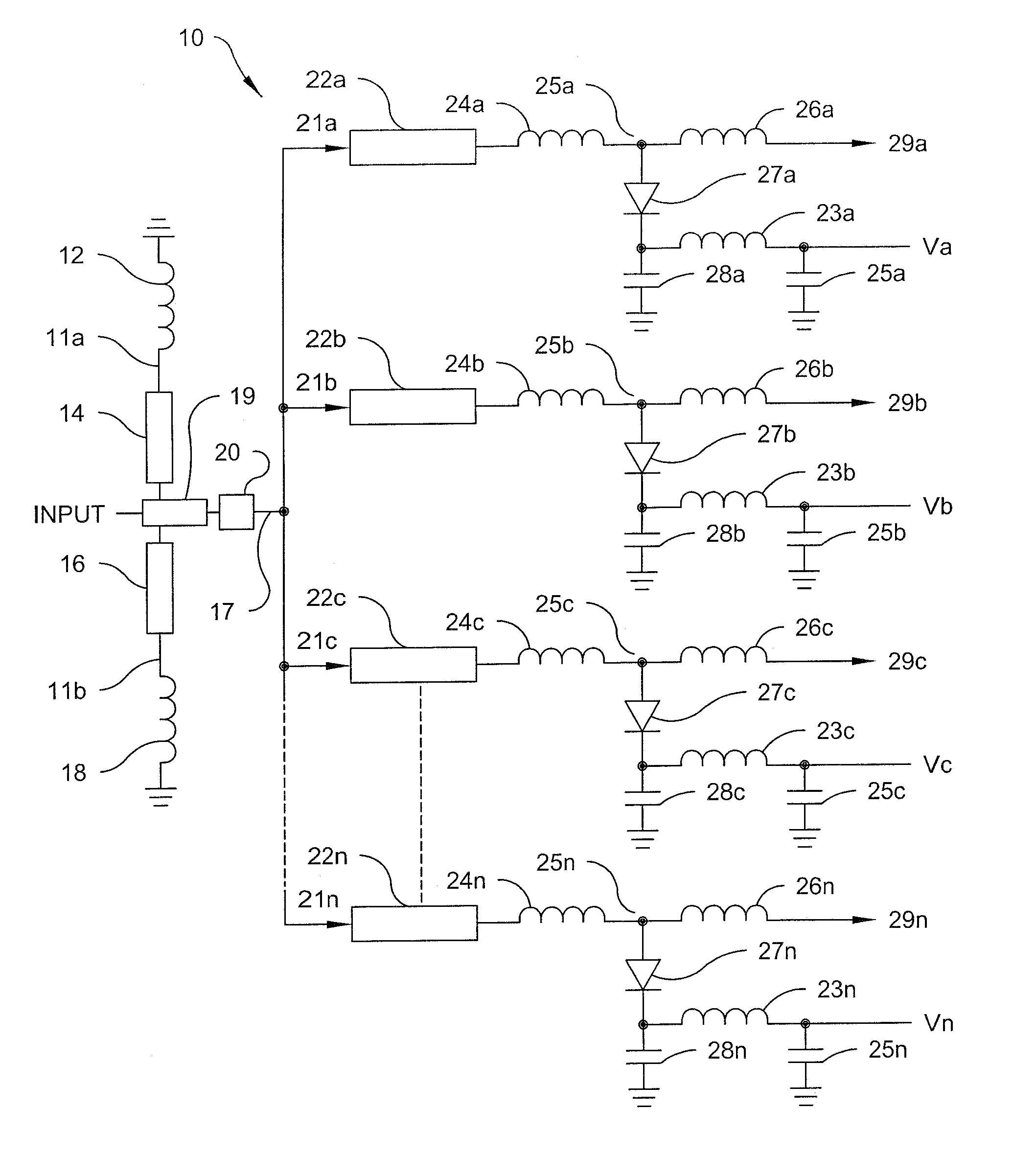
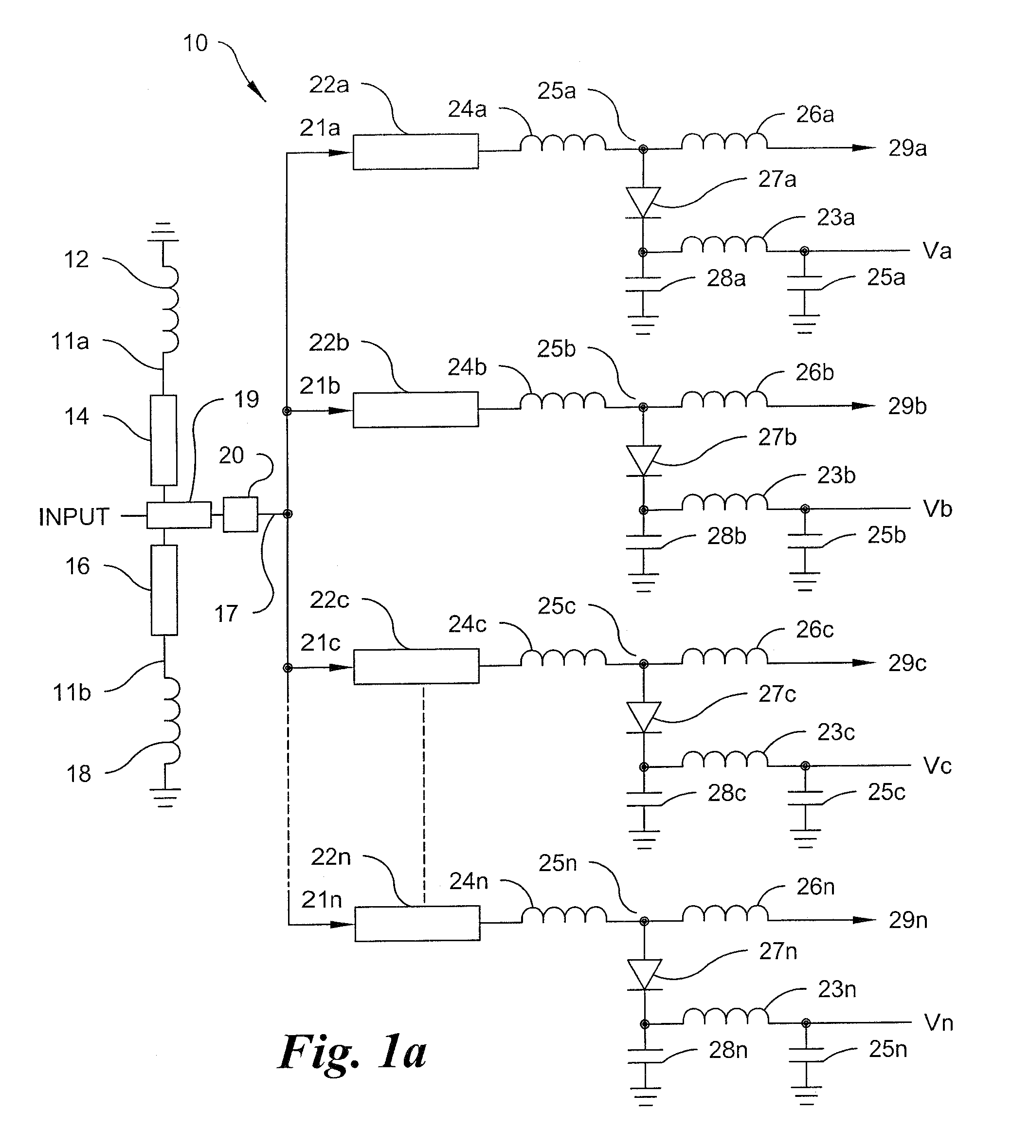
[0017]FIG. 1a is an electrical schematic of the switch according to an embodiment of the present invention. The RF high power single-pole multi-throw switch 10 provides for low insertion loss, high off-arm isolation, and low-risk switch bias / control injection to support RF operation in excess of 10 kW. As further describe...


PUM


Abstract

A single pole multiple-throw switch for switching an RF signal to one of a plurality of outputs includes coupling the signal to a throw junction, said junction having connected thereto a plurality of switch legs, each leg includes a high voltage shunt diode spaced one quarter-wavelength from the throw junction; each diode mounted at its cathode end to a capacitor and adapted to receive a bias; wherein a controller applies a first DC bias to a selected one of the diodes to cause the selected diode to operate in reverse bias mode, such that the selected diode mounted on the corresponding capacitor provides a low insertion loss to pass the RF signal from the transmission line through the selected leg and to one of the outputs; and applies a second DC bias to the other diodes to cause the other diodes to operate in forward bias mode such that the other diodes mounted onto the corresponding capacitor provides a high insertion loss for blocking the RF signal to the remaining outputs.

Description

FIELD OF INVENTION[0001]The present invention relates generally to electrical high frequency high power electronically controlled switches that pass high current at a low impedance.BACKGROUND[0002]Airborne radar systems have an ongoing requirement to switch high radio frequency (“RF”) signals. The prior art provides switches that are often contained in large packages and do not allow design flexibility insofar as electronic switch control. In fact, presently there exists a lack of commercially available high peak, high average power single pole, single or multi-throw switches capable of handling 10-25 kilowatt (“kW”) for use in electronic applications generally and more particularly airborne radar / electronic warfare applications. Furthermore, the prior art does not offer an Ultra High Frequency (“UHF”) switch in the same package as its digitally controlled circuits. Finally, the prior art offers no acceptable product that takes into account the multiple requirements of low insertion...

Claims


Application Information

Patent Timeline
Patent Type & Authority Applications(United States)
IPC IPC(8): H01P1/15
CPCH01P5/12H01P1/15
Inventor WOLFE, ALLEN R.LONG, ROBERT S.LOPACKI, JOHN C.
Owner LOCKHEED MARTIN CORP
Why Eureka
Try Eureka