Compact resonator fiber optic gyroscopes

a fiber optic gyroscope and compact technology, applied in the field of compact resonator fiber optic gyroscopes, rotation rate measurement apparatus, can solve the problems of large rotation sensing error, interference between reflected light and resonator output light on the cw detector, and errors in rotation rate measuremen

Active Publication Date: 2010-11-18
HONEYWELL INT INC
View PDF17 Cites 16 Cited by
  • Summary
  • Abstract
  • Description
  • Claims
  • Application Information

AI Technical Summary

Benefits of technology

[0006]The present invention provides for improved compact resonator fiber optic gyroscope systems that are symmetric, in transmission mode, and/or use

Problems solved by technology

The reflected light and the resonator output light interfere on the CW detector.
A problem associated with the architecture shown in FIG. 1 is that large rotation sensing errors are caused by the interference between an undesirable portion of the reflected light and the resonator output light.
Even after careful alignment, polarization dependent losses or spatial aperturing effects between the resonator input mirror and the detector can cause errors in the rotation rate measurement.
For example, imperfections in the input polarization state will result in line-shape asymmetry, which in turn will result in a gyro rate bias error.
However, this architecture is not symmetric in the CW and CCW directions because only some light in the CW direction propagates through the fiber coil prior to reaching the CW detector, while all of light in t

Method used


Image

  • Compact resonator fiber optic gyroscopes
  • Compact resonator fiber optic gyroscopes
  • Compact resonator fiber optic gyroscopes

Examples


Embodiment Construction

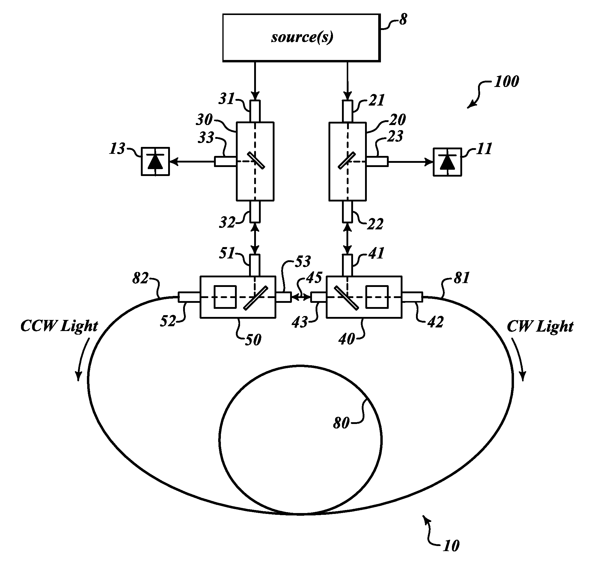
[0035]FIG. 4 shows a resonator fiber optic gyroscope (RFOG) 100 formed in accordance with an exemplary embodiment of the present invention. The RFOG 100 includes light source 8, directional optical components 20 and 30, resonator input / output coupling optical components 40 and 50, detectors 11 and 13, and a resonator 10 including a fiber loop 80. The light source 8 emits at least two beams of light: a beam of light for a CCW direction and another beam of light for the CW direction. Alternatively, light source 8 could include two independent light sources one providing light for the CCW direction and the other for the CW direction. Each of the directional optical components 20 and 30 includes an input port 21 and 31, an output port 22 and 32, and a detector port 23 and 33. A substantial portion of light received by the input port 21 and 31 is directed to the output port 22 and 32 but prevented from entering the detector port 23 and 33. In a reverse direction (indicated by an up-arrow...


PUM


Abstract

Substantially symmetric RFOG configurations for rotation rate sensing using two input/output coupling components. Configurations are disclosed where optical coupling components handles both input and output lightwaves. Reducing the number of input/output coupling components while maintaining a substantially symmetric configuration for the CW and CCW beam reduces losses, prevents realization of bias errors due to asymmetric light paths in the resonator, and produces better signal to noise performance. In addition, the invention discloses systems integrating multiple functions into compact micro-optic devices that are easier to fabricate and package, leading to compact RFOGs with reduced cost and improved manufacturability.

Description

BACKGROUND OF THE INVENTION[0001]A resonator fiber optic gyroscope (RFOG) is a rotation rate measurement apparatus that uses a fiber ring resonant cavity to enhance a rotation-induced Sagnac effect. The basic principle of RFOG operation is that the effective resonator round-trip path length in a clockwise (CW) and counter-clockwise (CCW) direction is different when the rotation has a nonzero component in a resonator axis. By measuring the CW and CCW resonance frequency difference, which is proportional to Sagnac phase shift due to rotation, the RFOG can accurately measure the rotation rate. Several RFOG configurations are suggested by the prior art. Three specific prior art resonator configurations are shown in FIGS. 1-3.[0002]FIG. 1 shows a resonator in reflection mode configuration, where light is introduced to a resonator formed by a resonator input mirror and a fiber optic resonator coil. The mirror has some reflectivity and a low, but non-zero, transmission coefficient. Thus, m...

Claims


Application Information

Patent Timeline
IPC IPC(8): G01C19/72
CPCG01C19/727
Inventor QIU, TIEQUNSTRANDJORD, LEESANDERS, GLEN A.
Owner HONEYWELL INT INC
Why Eureka
Try Eureka