Ultra-High Temperature Distributed Wireless Sensors

a wireless sensor and ultra-high temperature technology, applied in the field of sensors, can solve the problems of difficult efficiency of gasification plant operation, complex manufacturing of built-in electrical components, and difficulty in efficient operation of temperature sensors such as thermocouples, so as to improve the ability to tolerate thermal expansion and contraction, and protect from extremely high temperature and corrosive environment.

Inactive Publication Date: 2010-11-18
PRIME PHOTONICS LC
View PDF17 Cites 26 Cited by
  • Summary
  • Abstract
  • Description
  • Claims
  • Application Information

AI Technical Summary

Benefits of technology

[0010]In one embodiment, the inventive passive sensor includes a ceramic sheet, whose conductivity is dependent on temperature, sandwiched between two metal slot arrays. This stack is then hermetically sealed and encapsulated in a single crystal sapphire package

Problems solved by technology

Sustained, efficient operation of a gasification plant is challenging and requires that the plant operates at optimal temperature to crack the volatile hydrocarbons and to promote the thermo-chemical reactions that generate the syngas.
Temperature sensors such as thermocouples, optical pyrometers, optical sensors and acoustic sensors have been used but with limited success.
Buil

Method used


Image

  • Ultra-High Temperature Distributed Wireless Sensors
  • Ultra-High Temperature Distributed Wireless Sensors
  • Ultra-High Temperature Distributed Wireless Sensors

Examples


Embodiment Construction

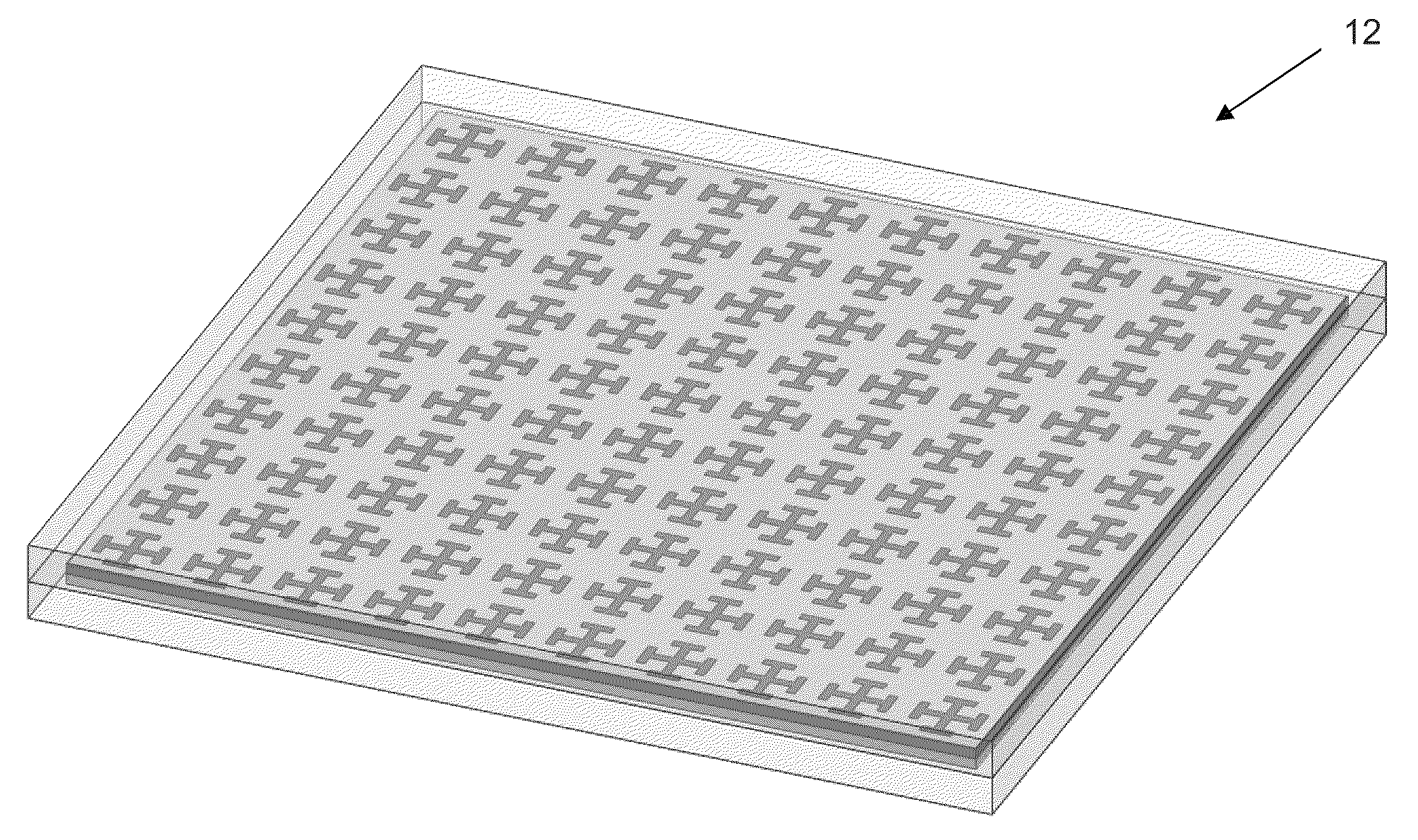
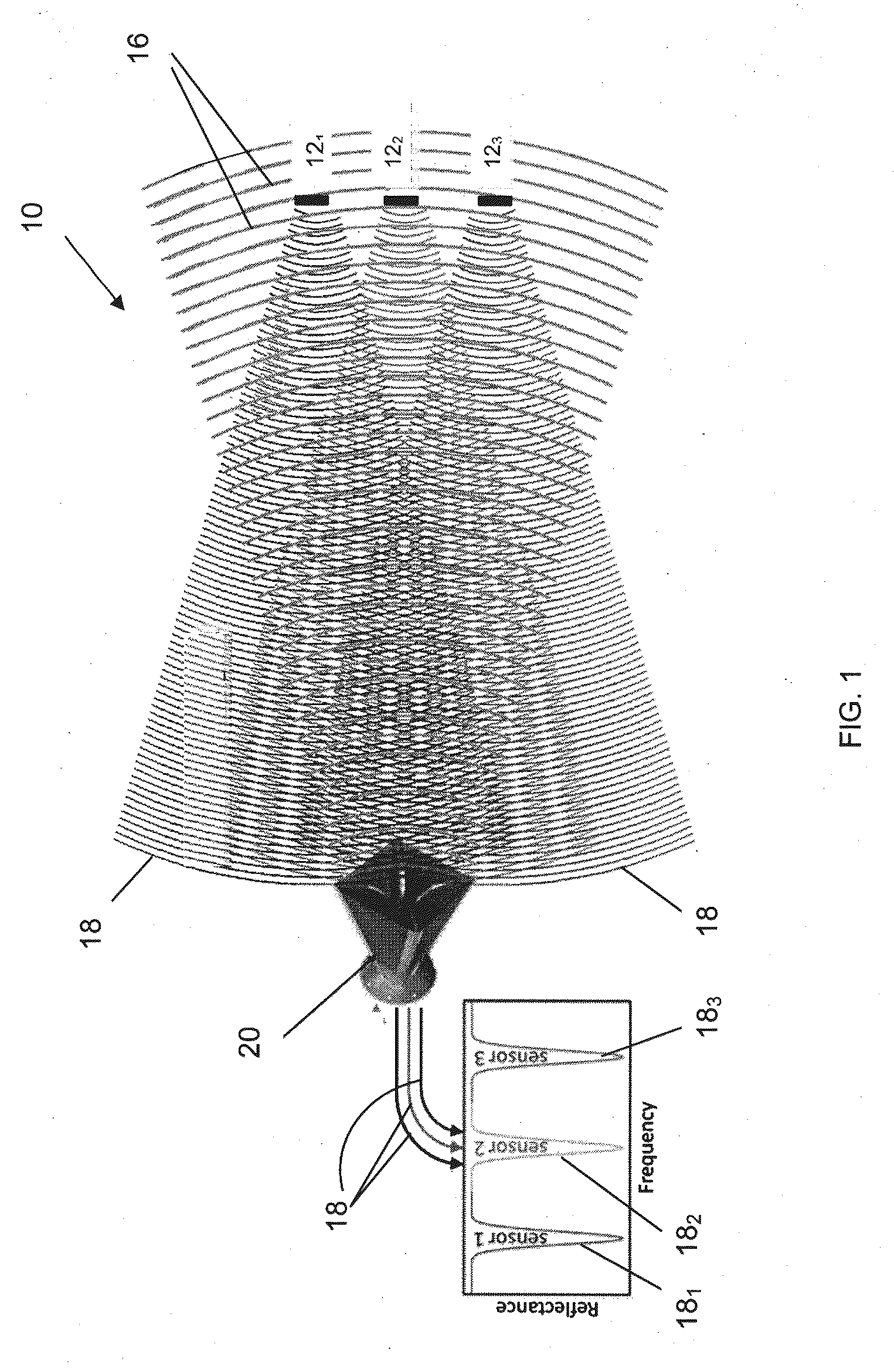
[0022]In one exemplary embodiment, the present invention comprises a wireless, remote sensor system 10 for measuring temperatures at multiple locations, particularly in high-temperature or inhospitable environments described above, in which a broadband interrogating source, preferably but not limited to radio frequency range (RF), interrogates an array of passive wireless sensors 12i distributed throughout a chamber such as a coal gasification chamber, as illustrated in FIG. 1. Three sensors 121, 122, and 123 are shown; however, the invention is not limited to any number of sensors. Each wireless, remote temperature sensor 12 comprises a temperature sensitive element and a frequency selective element, preferably a metamaterial, and the frequency selective element is selected to respond or scatter electromagnetic energy at or near its resonance frequency. As used herein, metamaterial includes man-made or engineered materials that generally gain their properties from their structure r...


PUM


Abstract

A passive wireless sensor is disclosed. The sensor has at least a measurand sensitive member and an electromagnetically resonant member positioned proximate to each other. The resonant member comprises a preselected resonance frequency, such that it scatters at least a portion of an interrogating signal as a scattered signal proximate to its resonance frequency, and the measurand sensitive member alters the scattered signal as a function of the measurand to change the shape of the scattered signal. The reactive field of the sensor is kept within the sensor to minimize environment interference and to maximize its signal strength. Almost bond-free packaging mitigates problems with delamination or internal stresses due to differing coefficients of thermal expansion.

Description

CROSS-REFERENCE TO RELATED PATENT APPLICATION[0001]The present patent application claims the benefit under Title 35, United States Code, §119(e) to U.S. provisional patent application Ser. No. 61 / 216,095 filed on 13 May 2009. Provisional application Ser. No. 61 / 216,095 is incorporated by reference herein in its entirety.FIELD OF THE INVENTION[0002]The present invention is related to a sensor to accurately measure various physical properties, such as temperature or pressure, in harsh or inhospitable environments. More specifically, the present invention is directed to a remote, passive sensor that primarily changes the shape of its resonance frequency curve in response to the measured property(ies).BACKGROUND OF THE INVENTION[0003]In ultra-high temperature environment, such as internal combustion engines, turbine engines, and coal gasification power plants where temperature reaches well above 1000° C., there exists a need to remotely monitor various measurands or parameters like temp...

Claims


Application Information

Patent Timeline
IPC IPC(8): G01K7/00G01L1/00G01R29/08
CPCG01L1/005G01K7/32
Inventor RUMPF, JR., RAYMOND CHARLESCOGGIN, JOHN MOOREPOLAND, STEPHEN HAMILTON
Owner PRIME PHOTONICS LC
Why Eureka
Try Eureka