Wireless communication system, receiver, transmitter, wireless communication method, receiving method, and transmitting method

a wireless communication and wireless communication technology, applied in the field of wireless communication systems, can solve the problems of reducing system gain, increasing device power consumption, and reducing system gain, so as to achieve accurate demodulation of signals and simple circuit configuration

Inactive Publication Date: 2010-11-18
NEC CORP
View PDF4 Cites 36 Cited by
  • Summary
  • Abstract
  • Description
  • Claims
  • Application Information

AI Technical Summary

Benefits of technology

[0036]According to the present invention, it is possible to provide a system that combines MIMO spatial multiplexing and dual polarization transmission, and to construct the system with a simple circuit configuration, thereby providing a wireless communication system which accurately demodulates signals that are multiplexed doubly, both spatially and in polarization.

Problems solved by technology

Increasing the number of modulation levels, however, has only a limited effect of capacity increase relative to an increase of what is called C / N (Carrier to Noise power ratio), resulting in the disadvantage of lower cost efficiency.
Widening the bandwidth reduces the system gain as much as the noise bandwidth, with the disadvantage of increased device power consumption.
High frequency bands of 60 GHz and above can be used to provide a wide band, whereas too high frequencies increase the parts cost and have the disadvantage of an extremely short transmission range due to radio wave absorption by the air.
Under the foregoing limitations, it has been difficult to further increase microwave or millimeter wave communication systems in capacity.
To achieve a further increase in capacity, however, there has been no means other than to increase the bandwidth.
Nevertheless, there is no mobile communications system that uses dual polarization.
It has heretofore been held that the same MIMO technologies as those of mobile systems are not applicable to microwave or millimeter wave communication systems for line-of-sight communications.
That is, in line-of-sight communication systems, MIMO-based parallel communication channels such as in practical use with mobile units do not hold.
The slight differences in the transmission distance, however, result in different phases due to the high frequency.
The principle has thus been impractical since such conditions easily fail to hold because of an error in the actual installation spacing between the antennas or due to small swings of the antennas in the wind or by vibration.

Method used


Image

  • Wireless communication system, receiver, transmitter, wireless communication method, receiving method, and transmitting method
  • Wireless communication system, receiver, transmitter, wireless communication method, receiving method, and transmitting method
  • Wireless communication system, receiver, transmitter, wireless communication method, receiving method, and transmitting method

Examples


example 1

[0080]Initially, the configuration and operation of the transmitting side (transmitting station, transmitting set, transmitting apparatus, or transmitting section) and the receiving side (receiving station, receiving set, receiving apparatus, or receiving section) of a communication system according to example 1 of the present invention will be described separately. As for the configuration related to MIMO signal processing, both the transmitting side and the receiving side are based on configuration example 4 that is shown in FIG. 5 of PTL 1 (where the unitary matrix of the communication channel matrix H is calculated on the receiving side; independent local oscillators for respective antennas are used both on the transmitting side and the receiving side).

[0081][Configuration of Transmitting Side]

[0082]FIG. 3 shows an example of configuration of the transmitting side of the communication system according to example 1.

[0083]The communication system shown in FIG. 3 includes the follo...

example 2

[0151]Next, a communication system according to example 2 of the present invention will be described with reference to FIGS. 9 and 10.

[0152]As can be seen from FIGS. 6 and 8 above, the MIMO signal processing and the XPIC signal processing both are linear operations. That is, the same result is obtained regardless of which is processed first. In the configuration of the receiving side of example 2, the XPICs are arranged prior to the MIMO signal processing circuits in an order inverse to example 1.

[0153]FIG. 9 shows an example of configuration of the receiving side of the communication system according to example 2.

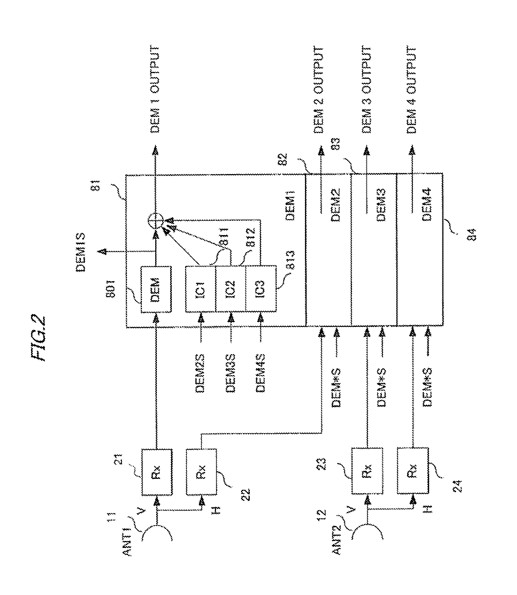
[0154]The receiving side of the communication system shown in FIG. 9 are almost the same components as in FIG. 4. Detailed description thereof will thus be omitted. As shown in FIG. 9, first and second antennas 11 and 12 are connected with receivers 21 to 24 for V-polarized signals and H-polarized signals, on the output side of which respective four interference canceling ...

example 3

[0167]FIG. 11 shows the configuration of the transmitting side (transmitting section) of a wireless communication system according to example 3 of the present invention. In the example of FIG. 11, the configuration of the transmitting side of the wireless communication system according to example 1 shown in FIG. 3 is applied to the transmitting side of configuration examples 1 and 2 described in PTL 1 (where the unitary matrix of the communication channel matrix His calculated on the transmitting side).

[0168]As with the configuration of FIG. 3 (example 1) seen above, the wireless communication system shown in FIG. 11 is a MIMO system (line-of-sight communication system) that has two transmitting antennas 13a and 13b on the transmitting side and two receiving antennas 11a and 11b on the receiving side, and forms mutually orthogonal fixed transmission channels between the transmitting side and the receiving side.

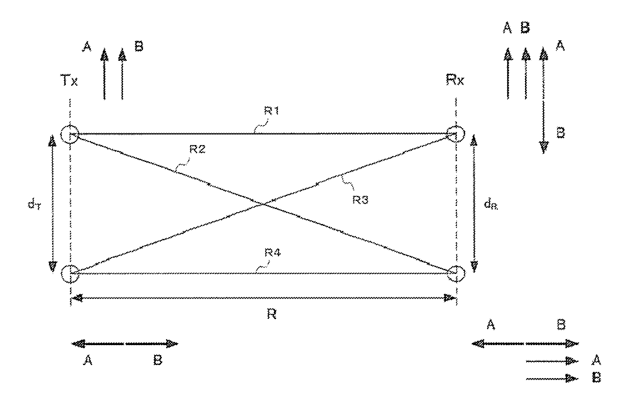
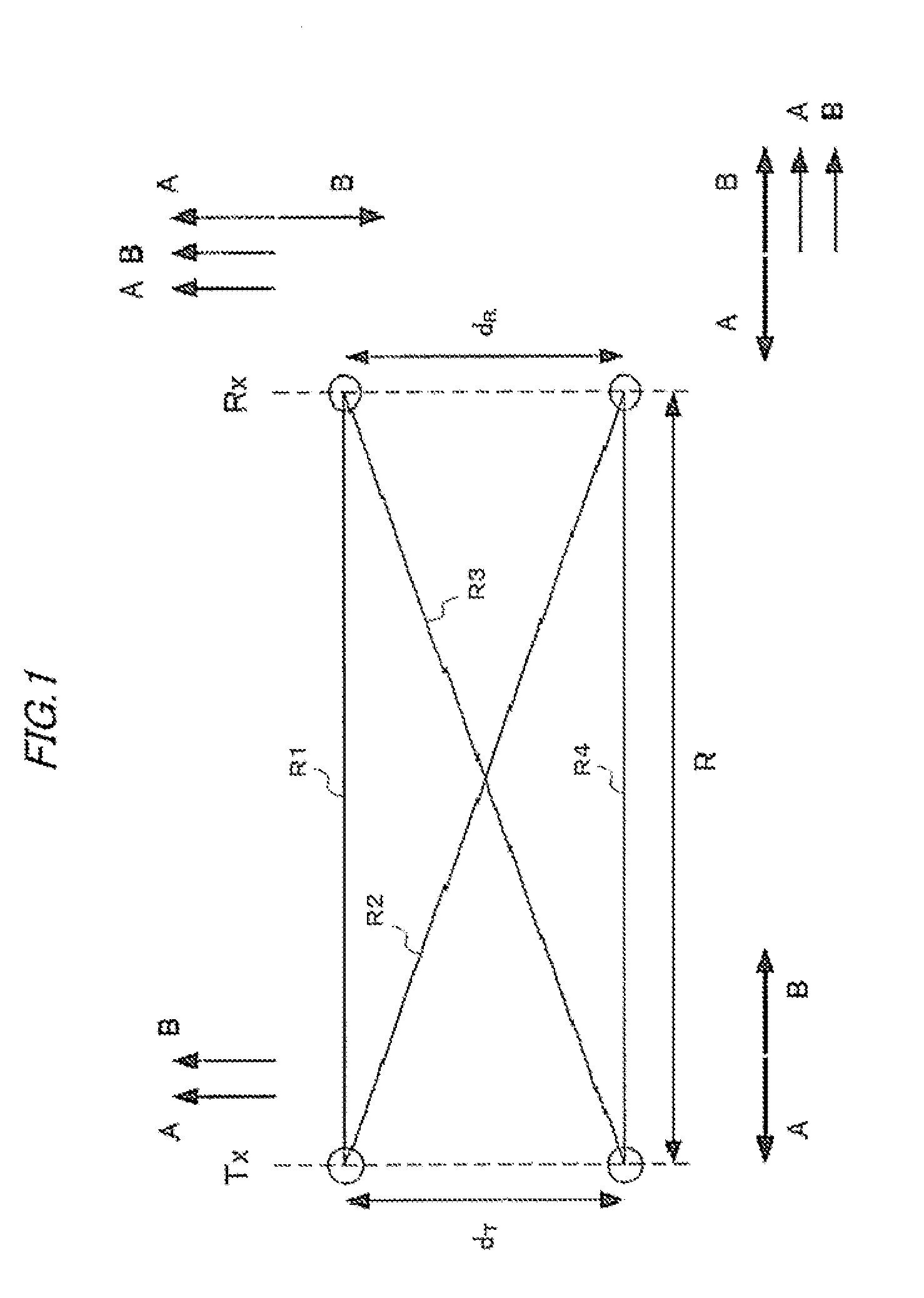
[0169]In FIG. 11, dT represents the installation distance (element distan...


PUM


Abstract

A system that combines MIMO spatial multiplexing and dual polarization transmission is provided. The system is constructed with a simple circuit configuration, whereby a wireless communication system which accurately demodulates signals that are multiplexed doubly, both spatially and in polarization, is provided. The wireless communication system is a MIMO communication system that uses a plurality of antennas to form a plurality of fixed transmission channels, and includes a transmitting section and a receiving section. The transmitting section performs MIMO spatial multiplexing as well as dual polarization transmission of transmitting two independent signals in the same band by using two mutually orthogonal polarizations of radio waves as signals to be transmitted from respective antennas on a transmitting side. The receiving section includes an inference canceller and a MIMO signal processing circuit that is connected to the interference canceller. The interference canceller performs signal processing for eliminating an interference component between the polarizations by adaptive control on signals received by respective antennas on a receiving side. The MIMO signal processing circuit performs signal processing for MIMO spatial demultiplexing independent of the signal processing of the interference canceller.

Description

TECHNICAL FIELD [0001]The present invention relates to a wireless communication system that uses microwaves or millimeter waves, and more particularly to a wireless communication system, a receiving apparatus, a transmitting apparatus, a wireless communication method, a receiving method, and a transmitting method for higher capacity transmission within a limited band.BACKGROUND ART [0002]Microwave or millimeter wave communication systems, which are line-of-sight communication systems with fixed transmitting and receiving stations, have recently been growing rapidly in demand as a mobile communications infrastructure. With the increasing traffic of the mobile communications, a further increase in the transmission capacity has been demanded.[0003]According to such a market demand, dual polarization transmission with XPICs (Cross Polarization Interference Cancellers), which have conventionally been used in trunk systems, have come into standard use. A typical high-capacity system at pr...

Claims


Application Information

Patent Timeline
Patent Type & Authority Applications(United States)
IPC IPC(8): H04L1/02H04L27/00
CPCH04B7/0413H04B7/0697H04B7/0871H04B7/0689H04B7/10
Inventor SASAKI, EISAKU
Owner NEC CORP
Why Eureka
Try Eureka