
Beverage machines, subsystems thereof and corresponding methods

a technology of beverage machines and subsystems, applied in the field of beverage machines, can solve the problems of inability to heat a flow of water from room temperature to near boiling, limited storage capacity of this arrangement, and inability to use heat-on-demand devices

Inactive Publication Date: 2010-11-25
COFFEE & JUICE GENERATION
View PDF5 Cites 14 Cited by
  • Summary
  • Abstract
  • Description
  • Claims
  • Application Information

AI Technical Summary

Benefits of technology

[0021]According to a further feature of the present invention, the dispensing program is implemented such that: (a) during a first period, a temperature of the thermal conduction block is adjusted from temperature T0 to within a given margin of the required temperature T; and (b) during a second period, the heating element is actuated as a function of a rate of flow of liquid through the elongated passageway to minimize temperature variations in the thermal conduction block while the liquid flows through the elongated passageway.
[0034]According to a further feature of the present invention, the controller is further configured to: (a) during a first period, adjust a temperature of the thermal conduction block from an initial temperature to within a given margin of the required temperature T; and (b) during a second period, actuate the heating element as a function of a rate of flow of liquid through the elongated passageway to minimize temperature variations in the thermal conduction block while the liquid flows through the elongated passageway.
[0055]There is also provided according to the teachings of the present invention, a powder dispenser for a beverage machine, the powder dispenser comprising: (a) a plurality of powder containers each having an opening for refilling the powder container and an auger dispensing mechanism for dispensing powder from the container via an outlet; and (b) a rotary support mechanism supporting the plurality of powder containers, the rotary support mechanism being rotatable about a substantially vertical axis, wherein the powder containers are deployed such that, for each powder container, a corresponding position of the rotary support mechanism brings the outlet of the powder container to a common dispensing location.
[0064]According to a further feature of the present invention, the cup supporting arm has a rigid cup-gripping configuration configured such that, when the cup supporting arm brings a cup to the lifting location, partial raising of the cup delivery elevator is effective to disengage the cup from the cup-gripping configuration and to allow pivotal motion of the cup supporting arm to move clear of the cup delivery elevator.

Problems solved by technology

It appears that the storage capacity of this arrangement is very limited.
In practice, heat-on-demand devices are not often used for a number of reasons.
Firstly, the power required to heat a flow of water from room temperature to near boiling is often prohibitive.
This would limit use of the device to locations provided with special power supply installations, and is not suitable for a general purpose beverage machine.
Additionally, any non-uniformity of the heating effect could be potentially hazardous if a local hot-spot generates enough heat to cause local boiling of the water and corresponding pressure build-up.
This takes significant space, is wasteful of energy, and tends to suffer from scale deposition.
Firstly, although the shelf life of fresh pasteurized milk under refrigeration is sufficiently long to last between machine servicing every two or three days, any drop of milk which is not refrigerated will quickly spoil and turn sour. Furthermore, any contact between such a drop of soured milk and the remaining refrigerated milk rapidly accelerates bacterial growth in the main body of the milk leading to all the milk spoiling rapidly. Use of such spoiled milk in dispensed drinks would render the drinks unpalatable and could be potentially dangerous.
A further problem in implementing a fresh milk dispensing system is that thorough cleaning is needed of all parts coming in contact with the milk every time the milk supply is replenished.
This is labor intensive, and may not be feasible in general purpose beverage machines where on-site servicing must be maintained to a minimum.
For these reasons, automated beverage machines typically employ only dried powdered milk, with a consequent reduction in the quality of the resulting drinks.
If the stirrer is not properly cleaned or dried between operations, there is a concern that the mixer could become a source of contamination for the system.
Finally, automated beverage machines provided in various locations require considerable resistance to vandalism.
For machines which dispense cups, a sizeable opening is necessarily required, thereby leaving the machine susceptible to attempts to reach inside through the opening or obstruct the opening.

Method used


Image

  • Beverage machines, subsystems thereof and corresponding methods
  • Beverage machines, subsystems thereof and corresponding methods
  • Beverage machines, subsystems thereof and corresponding methods

Examples


Embodiment Construction

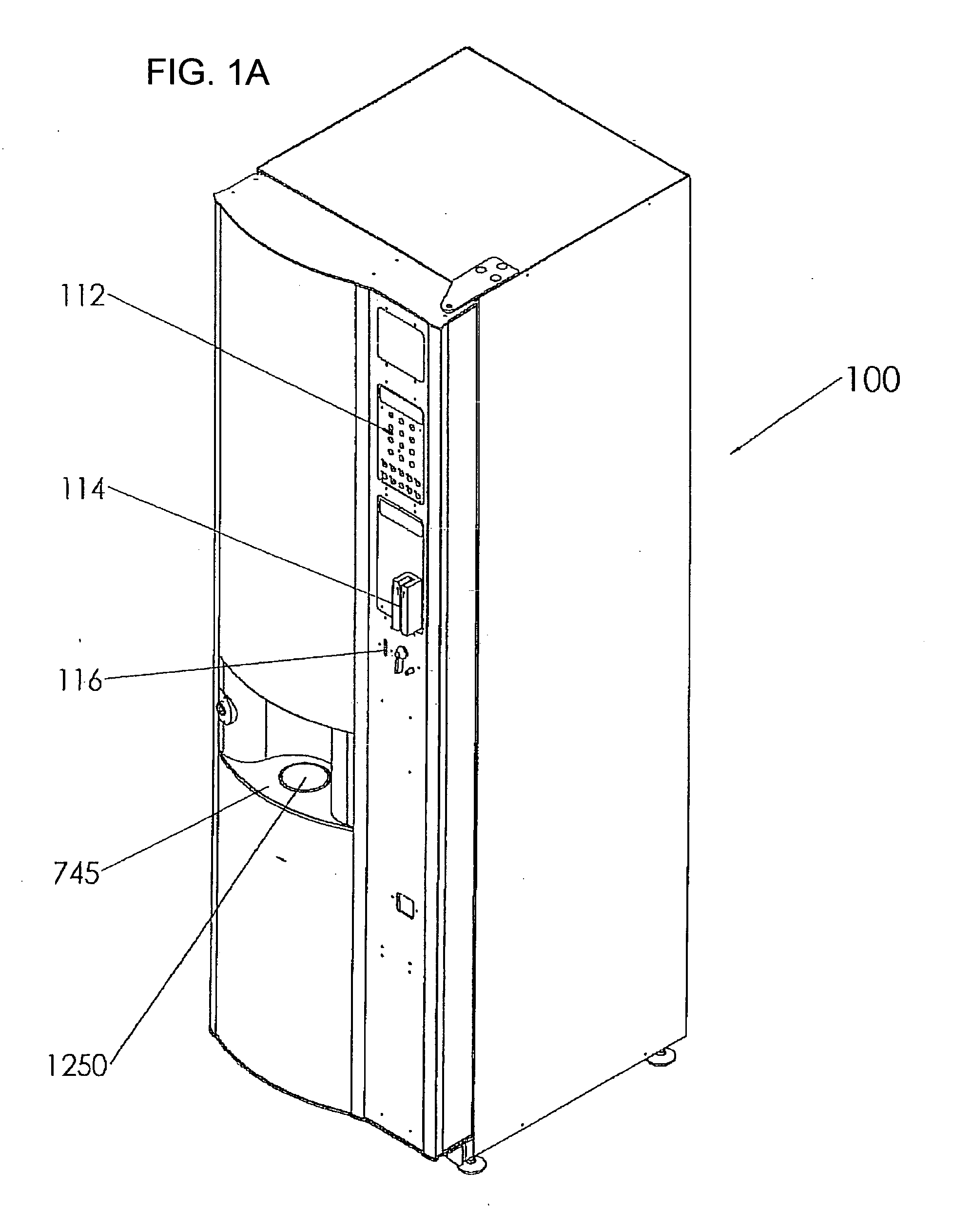
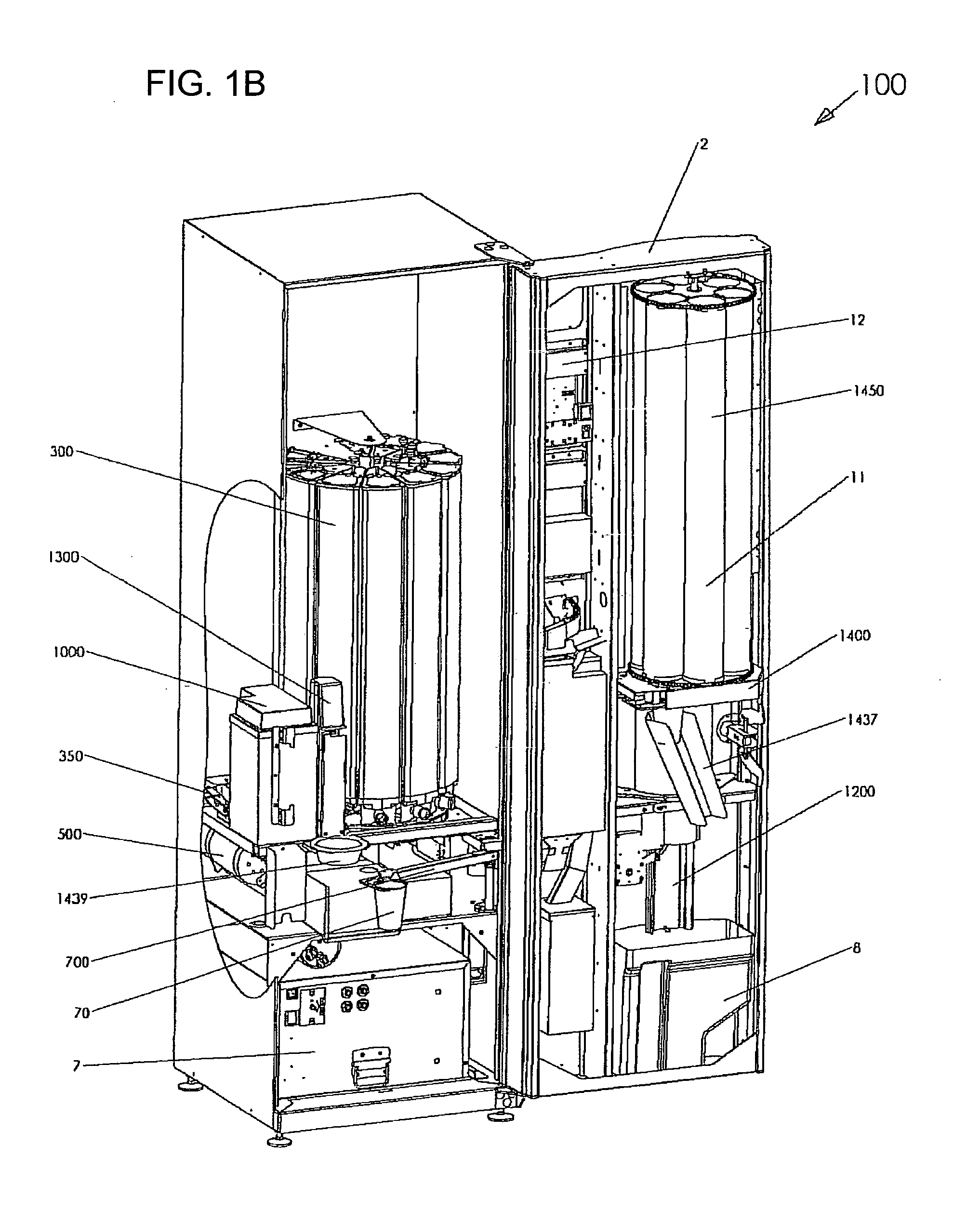
[0102]The present invention relates to a beverage machine, various subsystems thereof, and methods implemented therein.

[0103]The principles and operation of beverage machines, their subsystems and the corresponding methods according to the present invention may be better understood with reference to the drawings and the accompanying description.

[0104]By way of introduction, the beverage machine of the present invention includes a number of subsystems and implements a number of methods, each of which is believed to be patentable in its own right, but which are used to advantage in synergy according to a particularly preferred implementation of the present invention.

[0105]For clarity of presentation, the following description will be subdivided under separate headings relating to each of the subsystems of the beverage machine believed to be of particular significance. Specifically, a general overview of the structure and function of a particularly preferred embodiment of the beverage ...


PUM


Abstract

A mix-in-the-cup automated beverage dispensing machine includes a powder dispensing system with a rotary support structure bringing each powder container to a common dispensing location in turn. The machine also provides a water heater with a thermal conduction block and a method for heating water based on pre-calculation of the required heating profile. Also provided is a fresh milk dispensing system which maintains a fully cooled flow path from the container to the cup while ensuring that all components contacting the milk are disposable single-use components. Additional features discussed relate to a mixer unit cleaned by spinning within the cup, a structurally simple cup conveyance arrangement, and an cup elevator with geometrical locking.

Description

FIELD AND BACKGROUND OF THE INVENTION[0001]The present invention relates to beverage machines and, in particular, it concerns subsystems of a beverage machine useful for storing and dispensing powders, heating and dispensing water, storing and dispensing milk, stirring in a cup and delivering a cup to a user.[0002]While believed to be particularly advantageous when used together in synergy, the various aspects of the present invention are also of separate utility and will be best understood when described in the context of the relevant background. For this reason, both the background and the description will be subdivided according to the separate aspects of the invention.Storing and Dispensing Powders[0003]Many automated beverage machines employ powders which are dispensed and mixed with hot or cold water, or some other liquid, to produce the desired beverage. Typically, a plurality of different types of powder are stored within the machine for making a variety of drinks. The powde...

Claims


Application Information

Patent Timeline
Patent Type & Authority Applications(United States)
IPC IPC(8): B67D7/00H05B1/02B67D7/82
CPCA47J31/401
Inventor HIRSCHBAIN, SHLOMO
Owner COFFEE & JUICE GENERATION
Learn More