Energy recovering device with a liquid electrode

a liquid electrode and energy recovery technology, applied in the direction of influencing generators, electric devices, generators/motors, etc., can solve the problems of reducing the conversion efficiency of the device, reducing and reducing the device conversion efficiency, so as to simplify the making of the device and amplify the capacitance variation of the capacitor

Inactive Publication Date: 2010-11-25
COMMISSARIAT A LENERGIE ATOMIQUE ET AUX ENERGIES ALTERNATIVES
View PDF17 Cites 41 Cited by
  • Summary
  • Abstract
  • Description
  • Claims
  • Application Information

AI Technical Summary

Benefits of technology

[0018]In a first embodiment, the device may include a mobile element positioned opposite to the fixed electrode relatively to the dielectric layer and capable of moving away from and moving closer to the fixed electrode, the liquid electrode being interposed between the dielectric layer and the mobile element, the liquid electrode bei

Problems solved by technology

These devices are relatively efficient; however they have a major drawback: the risk of contact between the plates.
This contact may generate a short circuit on the one hand, and generate mechanical damping on the other hand, reducing the conversion efficiency of the device.
Further, this contact may cause degradation of the device.
Now the devices described above do not allow such a recovery in

Method used


Image

  • Energy recovering device with a liquid electrode
  • Energy recovering device with a liquid electrode
  • Energy recovering device with a liquid electrode

Examples


first embodiment

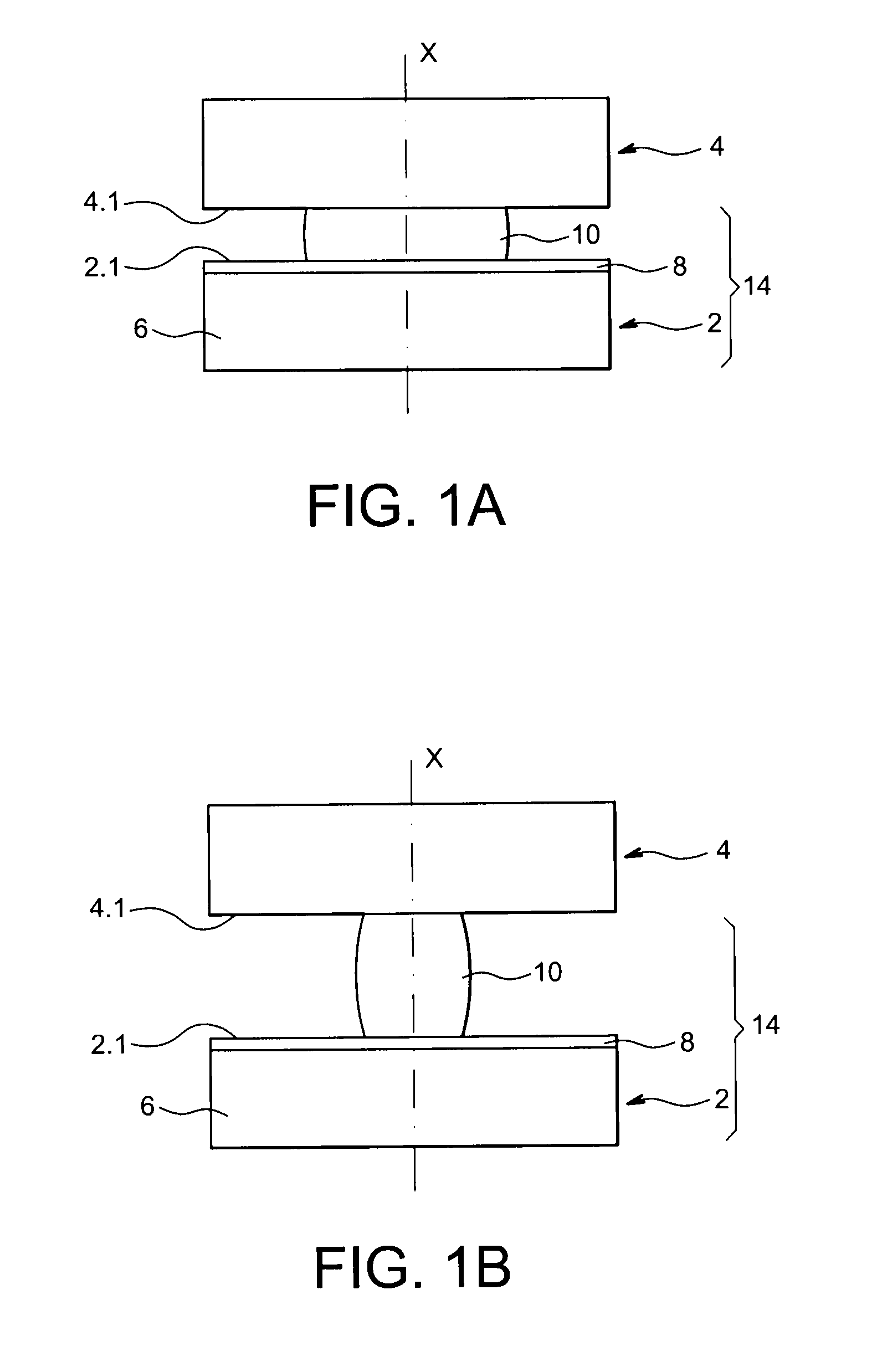
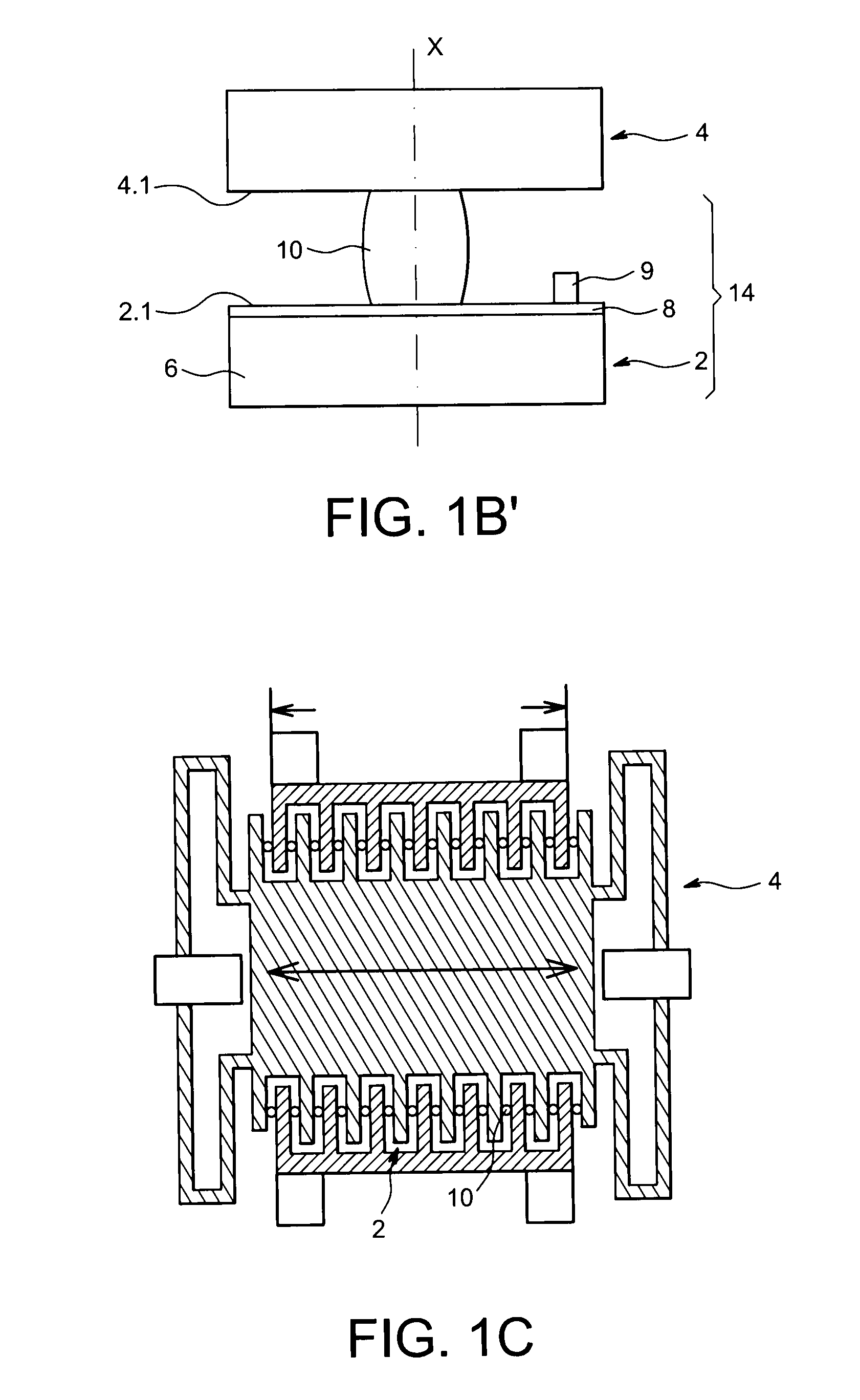
[0063]In FIGS. 1A and 1B, a first embodiment may be seen of an energy conversion device according to the present invention including a fixed element 2 and a mobile element 4, both elements 2, 4 including substantially planar faces 2.1, 4.1 respectively facing each other, the face 4.1 being intended to move closer to the face 2.1 and to move away from it. For this purpose, the mobile portion 4 is capable of moving along an axis X substantially orthogonal to the faces 2.1, 4.1.

[0064]The fixed element 2 includes a base 6 in an electrically conductive material in order to be used as an electrode or a plate for a capacitor, and an insulating electrical material layer and, preferably with strong electric permittivity 8, deposited on one face of the base 6 so as to form the planar face 2.1.

[0065]According to the present invention, an electrically conductive liquid element 10 is introduced between the fixed element 2 and the mobile element 4, more particularly between the dielectric layer 8...

second embodiment

[0101]In FIG. 2, an example of the present invention may be seen, wherein the variation of capacitance is obtained by displacing a liquid element.

[0102]In the example illustrated, it is desired to recover the kinetic energy and the potential energy of a liquid drop 102 flowing along a tilted plane 104.

[0103]This device includes a fixed electrode 106, fixed on one face of the tilted plane 104 opposite to the one with which the drop of liquid 102 comes into contact.

[0104]The tilted plane is made in an electrically insulating material advantageously with high permittivity 109, this material therefore electrically insulates the fixed electrode 106 from the drop 102, at least at the fixed electrode 106. This plane advantageously has a strongly hydrophobic surface and with low wetting hysteresis, which allows reduction of friction losses.

[0105]The device also includes an electric conductor 108 in the form of a tensioned filament above the tilted plane and following its slope.

[0106]The dev...

third embodiment

[0137]In FIG. 6A, a second alternative of the third embodiment according to the present invention may be seen, wherein the drops of liquid are moved under the action of pressure and no longer under the effect of gravity.

[0138]The device is supplied with drops of liquid by a reservoir 200.

[0139]This reservoir 200 is intended to supply the discharge pipe with a pressurized liquid / gas mixture, this reservoir may for example be formed by a water fall or by biphasic flow in a pipe, only one of the phases of which is electrically conducting.

[0140]The device includes a discharge channel 201. Similarly to the device of FIG. 5, an insulating fixed electrode 206 is positioned outside the channel 201, an injection electrode 215 is substantially positioned facing the fixed electrode 206 and forming a portion of the wall of the channel 201 and a removal electrode 216 is positioned downstream from the fixed electrode 206 in the direction of displacement of the drops 202 symbolized by the arrow 20...


PUM


Abstract

An energy recovery device including: at least one capacitor with variable capacitance, the capacitor including a fixed electrode, a dielectric layer, and a liquid electrode; and a mechanism to inject an electric charge into the capacitor and to remove the electric charge therefrom, including a charge injection electrode forming a portion of the second face positioned upstream from the fixed electrode in the direction of displacement of the liquid electrode, and a charge removal electrode forming a portion of the second face positioned downstream from the fixed electrode in the direction of displacement of the liquid electrode.

Description

TECHNICAL FIELD AND PRIOR ART[0001]The present invention relates to an energy recovering device applying at least one liquid electrode, more particularly to a device for converting mechanical energy into electrical energy.[0002]It is known how to convert vibratory energy into electrical energy, for example from the document <<Vibration-to-Electrical energy Conversion>>, Scott Meninger, Jose Oscar Mur-Miranda, Rajeevan Amirtharajah, Anantha P. Chandrakasan, and Jeffrey H. Lang, in IEEE Transactions on very large Scale Integration (VLSI) Systems, Vol. 9, No. 1, February 2001. The latter describes an energy conversion device formed with a plurality of capacitors with variable capacitance. The device includes two interdigitated combs, one of which is fixed and the other one is mobile under the effect of vibration. A first plate of each capacitor is borne by a finger of a comb and a second plate is borne by a finger of the other comb facing the first plate. Thus, when the mob...

Claims


Application Information

Patent Timeline
IPC IPC(8): H02N1/08
CPCH02N1/08
Inventor DESPESSE, GHISLAINFOUILLET, YVES
Owner COMMISSARIAT A LENERGIE ATOMIQUE ET AUX ENERGIES ALTERNATIVES
Why Eureka
Try Eureka