Ultrasonic motor driving method

a technology of ultrasonic motors and driving circuits, applied in piezoelectric/electrostrictive/magnetostrictive devices, piezoelectric/electrostrictive/magnetostrictive devices, piezoelectric/electrostrictive/magnetostrictive devices, etc., can solve the problems of increased difficulty in designing power supply and motors, and achieve simplified driving circuits, reduced voltage amplitude of power supply, and improved efficiency

Inactive Publication Date: 2010-11-25
BOLY MEDIA COMM SHENZHEN
View PDF5 Cites 10 Cited by
  • Summary
  • Abstract
  • Description
  • Claims
  • Application Information

AI Technical Summary

Benefits of technology

[0059]The advantage of the ultrasonic motor driving method according to the present invention is that only six switching transistors are required. The polarization in sequence of “++−−” may decreases the voltage amplitude of the power supply. Thus the driving circuit is simplified and the efficiency thereof could be improved, and thus the cost is reduced. It is especially advantageous for the ultrasonic motor to be used in the handheld devices powered by batteries.
[0060]Another advantage of outputting a voltage of two-phase in orthogonal by the three-phase bridge circuit is that this circuit may also output a voltage of three-phase in symmetry by another control method. As a result, when the piezoelectric motor is a three-phase structure or a two-phase / three-phase compatible structure, the motor may be driven by a voltage of three-phase. Therefore, a same set of driving circuit provides another option for the same motor, or the same set of driving circuit drives two or more rotors of the same kind.
[0061]The advantage of outputting a voltage of two-phase in orthogonal by the three-phase bridge circuit is that only six switching transistors are required. The circuit is simple so as to be integrated, with the automatically balanced input current, little fluctuation of the output torque, and abroad application prospect.
[0062]The advantage of using a dual half-bridge direct ripple circuit as the power supply is that the number of switching tubes and the volume of the power supply are reduced.
[0063]The advantage of two boost DC / DC switching circuit as a driving circuit is that, only four transistors are required together with proper peripheral circuit, so as to drive the ultrasonic motor. Furthermore, as the direct signal is outputted, the switching frequency of the transistor could be improved significantly, such as, to hundreds of kHz or million of kHz, such that the induction and capacitance required by the boost DC / DC switching circuit and its volume are reduced to promote the miniaturization and integration of the driving circuit. Even in a certain situation, the two transistors used to discharge the piezoelectric elements may be omitted to obtain the most simply circuit, such that the electric energy of the ultrasonic motor can further be feed back to the power supply such that the motor operates at two quadrants.

Problems solved by technology

In particular, for handheld devices powered by batteries, the difficulty in designing the power supply is increased.
When the battery voltage is fixed and the amplitude of the voltage input to the motor increases, the boost ratio of the boost DC / DC switching circuit increases accordingly, such that the motor is more difficult to be realized.

Method used


Image

  • Ultrasonic motor driving method
  • Ultrasonic motor driving method
  • Ultrasonic motor driving method

Examples


example 1

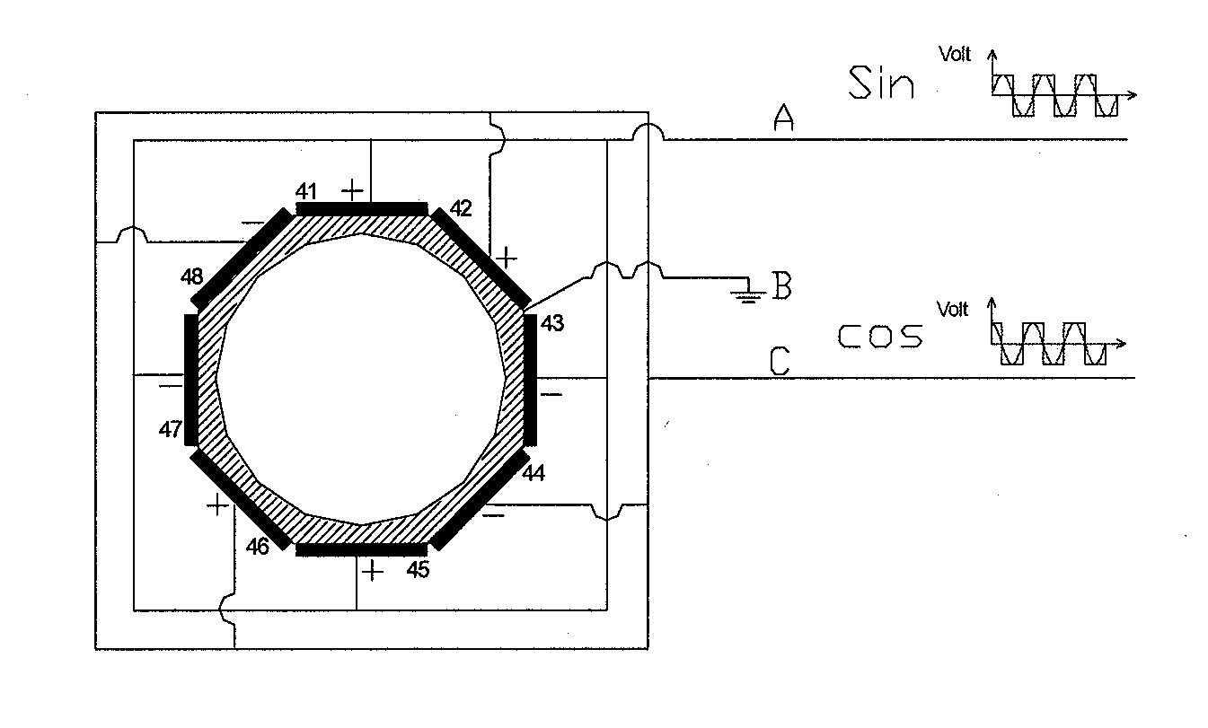
[0117]According to FIG. 3, the ultrasonic motor in the example comprises a stator 31 and a rotor 33, both of which are provided with a central circular hole. The stator 31 has a hollow cylindrical metal body and a plurality of piezoelectric elements 32 secured thereon. The rotor 33 comprises a revolving shell within which an optical lens assembly 34 is embedded. The body of stator 31 is matched with the rotor 33 through the screw thread 35. That is, the internal wall of the central circular hole of the stator 31 is provided with internal screw thread, while the external surface of the rotor 33 is provided with the corresponding external screw thread. The two threads have the same pitch and a nominal diameter. The body of the stator 31 has a shape of polyhedron or cylinder, as well as a hollow internal wall. Due to the metal material of the stator 31, the piezoelectric elements 32 thereon have a common node, which is called the common ground terminal. The surface of the screw thread ...

example 2

[0120]The solution according to Example 2 differs from that of the example 1 in that only the circuit for driving the power supply is different. As shown in FIG. 7, a boost DC / DC switching circuit is disposed preceding the bridge inverting circuit as shown in FIG. 5b so as to boost the supply voltage. For example, while using a battery as the power supply, the voltage from the battery is boosted by the boost DC / DC switching circuit to a voltage of particular value.

[0121]Of course, if the supply voltage is higher than the driving voltage required by the piezoelectric element, the voltage could be decreased by a buck DC / DC circuit similarly.

example 3

[0122]The ultrasonic motor according to Example 3 of the present application is shown in FIG. 8. The motor according to the example 3 of the present application differs from that in FIG. 3 in that only the number of the piezoelectric elements is different. In particular, the motor according to the example 3 of the present application has 6 piezoelectric elements, such that the motor is driven using a power supply of three-phase as will be discussed below.

[0123]The polarization of the piezoelectric elements and the wiring of the driving power supply are shown in FIG. 9. Piezoelectric patches 92-94 and 96-98 are all polarized in forward direction, and then connected to the midpoints of the first second and third legs 51, 52 and 53 in the circuit as shown in FIG. 5b. After that, the piezoelectric patches are activated and generate vibrating traveling waves rotating in the clockwise direction. The traveling waves drive the rotor to rotate under the friction therebetween. When the stator...


PUM


Abstract

An ultrasonic motor driving method, which drives the piezoelectric elements into two-two or three-three groups; within two-two group, one of the output terminals of the first and second piezoelectric elements are connected to the first and third nodes respectively, and the other terminals of the first and second piezoelectric elements are both connected to the second node which is the common ground terminal, the adjacent piezoelectric elements in one two-two group are polarized in sequence of “++−−”. Within three-three group, one of the output terminals of the first to third piezoelectric elements are connected to the first to third nodes respectively, and the other terminals of the first to third piezoelectric elements are all connected to the fourth node which is the common ground terminal, all piezoelectric elements are polarized in forward direction. Alternating voltage of two-phase in orthogonal or three-phase in symmetry is obtained by controlling the three-phase bridge inverting circuit to power each piezoelectric element. Therefore the voltage amplitude of the power supply and the number of transistors could be decreased effectively, and as a result the efficiency of driving circuit could be improved.

Description

CROSS REFERENCE TO RELATED APPLICATIONS[0001]The present application is a continuation application of International Application No. PCT / CN2008 / 001588, filed on Sep. 5, 2008, which claims priority of Chinese Patent Application No. 200710124086.9, filed on Oct. 26, 2007, all of which are incorporated herein by reference.TECHNICAL FIELD[0002]The present invention relates to a method for driving an ultrasonic motor.TECHNICAL BACKGROUND[0003]The ultrasonic motor is a driving mechanism which is formed by using the inverse piezoelectric effects of piezoelectric materials to incorporate a plurality of piezoelectric elements into a particular structure. It generally comprises functional components, such as a stator and a rotor etc. Piezoelectric elements having electrostrictive effects are fixed to the stator. The ultrasonic motor in the prior art is generally provided with four (or an integral multiple of four) piezoelectric elements, and driven by a sinusoidal power supply of four-phase or...

Claims


Application Information

Patent Timeline
Patent Type & Authority Applications(United States)
IPC IPC(8): H02N2/14
CPCH02N2/147H02N2/0095H02N2/163
Inventor LI, YIPENG, YONGHU, XIAOPING
Owner BOLY MEDIA COMM SHENZHEN
Why Eureka
Try Eureka