
Image forming lens, camera device, and handheld terminal

a technology of image forming lens and handheld terminal, which is applied in the field of lenses, camera devices, and handheld terminals, can solve the problems of chromatic aberration of magnification, distortion aberration, and inability to fully open the aperture stop, and achieve the effect of small siz

Inactive Publication Date: 2010-11-25
RICOH KK
View PDF4 Cites 34 Cited by
  • Summary
  • Abstract
  • Description
  • Claims
  • Application Information

AI Technical Summary

Benefits of technology

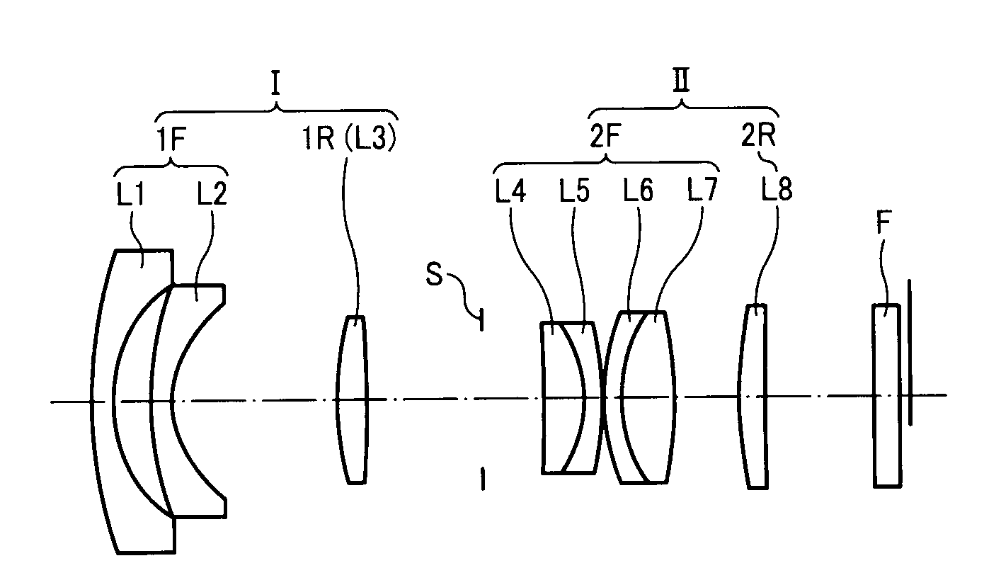
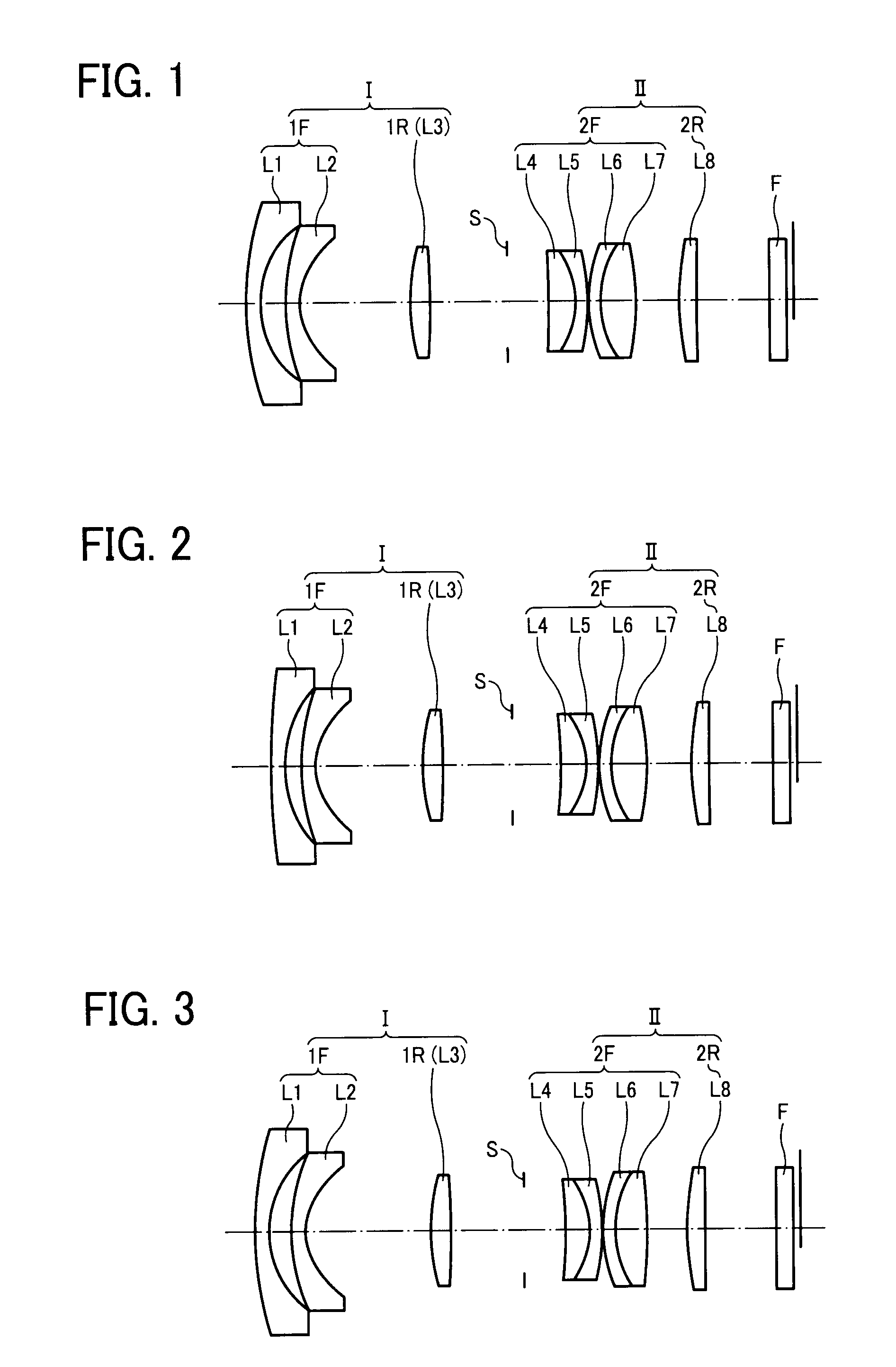
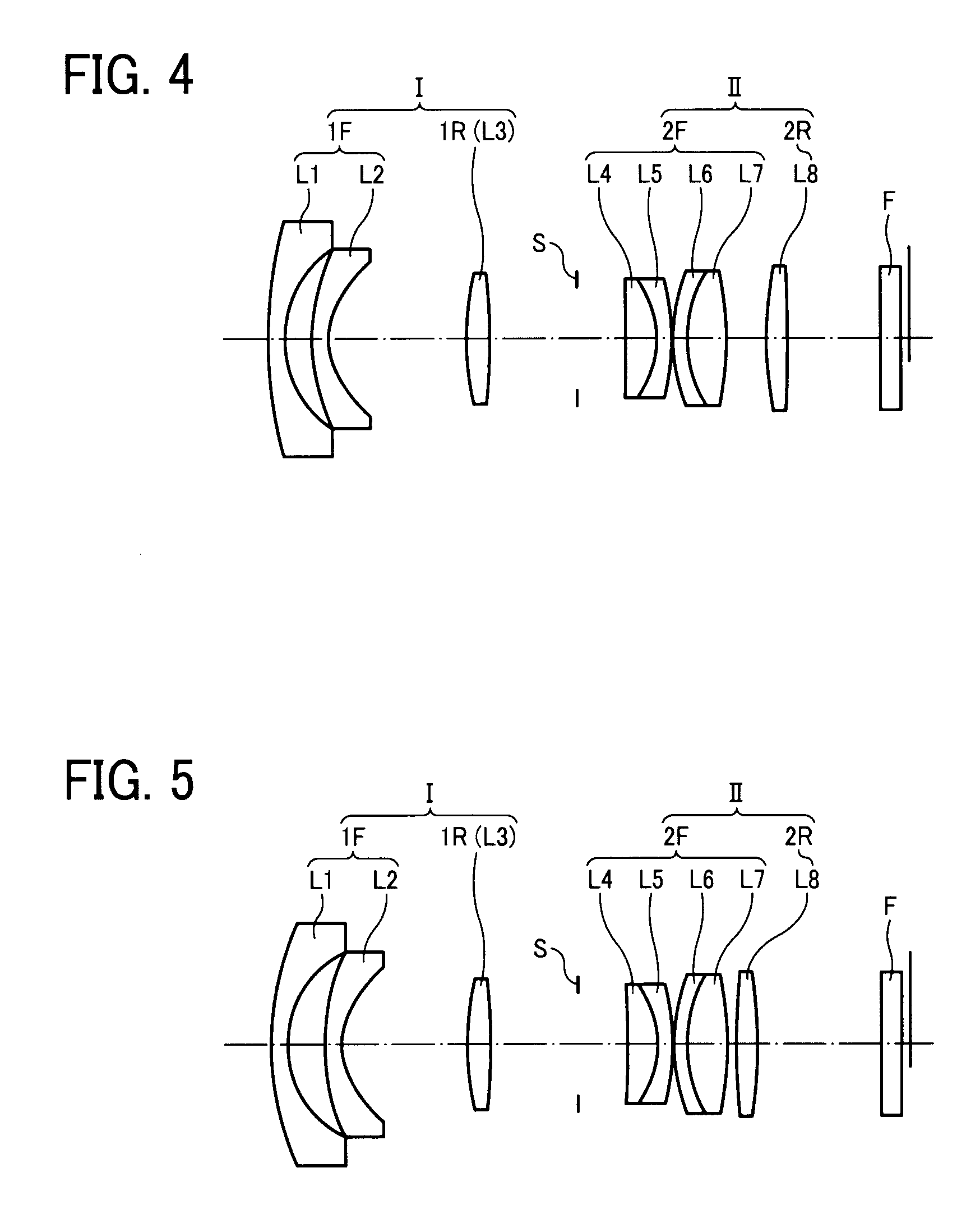
[0026]For these reasons, the present inventors recognize that a need exists for high performance image focusing lens suitable for a digital camera and a digital video camera that has a wide half angle of about 38 degree and a large diameter with an f number of around 2.0 or less (meaning a relatively small size with a large diameter) while astigmatism, field curvature, chromatic aberration of magnification, color difference of coma aberration, and distortion aberration are sufficiently reduced to deal with a resolution corresponding to an image pick-up element of 10,000,000 to 20,000,000 pixels with less coma flares when the aperture stop is fully open, less point image collapses to the periphery of the field angle of view under high contrast, less chromatic aberration resulting in no unneeded coloring in a portion having a large luminance difference, and less distortion aberration under which a straight line can be depicted as a straight line without distortion.
[0028]Accordingly, an object of the present invention is to provide a high performance image focusing lens suitable for a digital camera and a digital video camera that has a wide half angle of about 38 degree and a large diameter with an f number of around 2.0 or less (meaning a relatively small size with a large diameter) while astigmatism, field curvature, chromatic aberration of magnification, color difference of coma aberration, and distortion aberration are sufficiently reduced to deal with a resolution corresponding to an image pick-up element of 10,000,000 to 20,000,000 pixels with less coma flares when the aperture stop is fully open, less point image collapses to the periphery of the field angle of view under high contrast, less chromatic aberration resulting in no unneeded coloring in a portion having a large luminance difference, and less distortion aberration under which a straight line can be depicted as a straight line without distortion and a camera device and a handheld terminal that contains its image forming lens described above inside the body thereof when not in use.

Problems solved by technology

However, the retrofocus type has a large refractive power arrangement asymmetry, which tends to cause incomplete correction of coma aberration, distortion aberration, chromatic aberration of magnification, etc.
Although the image focusing lenses described in JP H06-308835-A have a large diameter (F1.4), astigmatism and field curvature of the lenses are also large, meaning that performance at the periphery when the aperture stop is fully open tends to be problematic.
Thus, the lens is thought to be not suitable for an image pick-up element of 10,000,000 to 20,000,000 pixels.
Thus, although generally successful, the lens having a small f number as described in JP 2006-349920-A is slightly insufficient considering the level of compactness now required.
In addition, correction of astigmatism, field curvature, and chromatic aberration of magnification is insufficient in terms of the lens performance out to the peripheral.
In addition, the field curvature of the lens is too large to secure good performance out to the periphery.
Furthermore, a great many lenses are required and thus size reduction is not easy to achieve.
However, an increase of the diameter of the lens leads to an increase in the number of the lenses in the system, resulting in an increase in the total thickness of the lenses.
Thus, the length of the lens barrel increases irrespective of any reduction in the space between the lens groups and / or the lenses on the optical axis by the storing mechanism, with the result that the lens barrel may not be sufficiently contained in the camera body.

Method used


Image

  • Image forming lens, camera device, and handheld terminal
  • Image forming lens, camera device, and handheld terminal
  • Image forming lens, camera device, and handheld terminal

Examples


example 2

[0344]f=6.00 F1.80 ω=39.1

[0345]Data of Example 2 are shown in Table 3.

TABLE 3RDNνHglass 161.0511.201.4970081.548.0S-FPL51 (OHARA) 29.7541.336.4 316.3001.201.5163364.066.3L-BSL7 (OHARA) 4*4.9339.505.2 518.7121.771.8160046.624.4S-LAH59 (OHARA) 6−49.7806.074.2 7Aperture4.083.7Stop 8−42.5532.221.4970081.543.6S-FPL51 (OHARA) 9−6.6301.001.6989530.133.7S-TIM35 (OHARA)10−16.6910.203.91112.0971.001.7282528.464.4S-TIH10 (OHARA)129.3183.081.4970081.544.4S-FPL51 (OHARA)13−26.1483.874.614*16.4941.501.5163364.064.8L-BSL7 (OHARA)15132.1605.714.816∞1.501.5000064.004.8Filter, etc.17∞0.604.8

Aspheric Surface

[0346]The data for the aspheric surfaces are shown below.

Fourth Surface

[0347]K=−0.40, A4=−4.07064E-04, A6=−9.23532E-06, A8=−7.96701E-08, A10=−3.61167E-09, A12=−3.61500E-11, A14=2.19580E-14, A16=8.93836E-15, A18=−1.95337E-15

Fourteenth Surface

[0348]A4=−3.58070E-04, A6=5.60374E-07, A8=−1.61334E-07, A10=1.41953E-09

Parameter Values of Relationship

[0349]The parameter values of each relationship are shown...

example 3

[0350]f=6.00 F1.90 ω=39.1

Data of Example 3 are shown in Table 5.

TABLE 5RDNνHglass 129.2701.201.4970081.548.5S-FPL51 (OHARA) 28.6861.936.6 316.3001.301.5163364.066.5L-BSL7 (OHARA) 4*4.99610.825.3 518.0931.741.8160046.624.4S-LAH59 (OHARA) 6−65.9586.334.2 7Aperture3.503.62Stop 8−117.2842.161.4970081.543.7S-FPL51 (OHARA) 9−7.2761.081.6989530.133.8S-TIM35 (OHARA)10−20.4370.203.951112.3801.001.7282528.464.4S-TIH10 (OHARA)129.0732.731.4970081.544.4S-FPL51 (OHARA)13−34.7163.414.514*17.2131.501.5163364.064.8L-BSL7 (OHARA)15198.6526.294.816∞1.501.5000064.004.8Filter, etc.17∞0.604.8

Aspheric Surface

[0351]The data for the aspheric surfaces are shown below.

Fourth Surface

[0352]K=−0.40, A4=−3.72757E-04, A6=−5.62333E-06, A8=−2.23363E-07, A10=−7.20448E-10, A12=−3.61500E-11, A14=2.19580E-14, A16=8.93836E-15, A18=−1.95337E-15

Fourteenth Surface

[0353]A4=−3.07134E-04, A6=2.41618E-06, A8=−1.97489E-07, A10=2.81138E-09

Parameter Values of Relationship

[0354]The parameter values of each relationship are shown i...

example 4

[0355]f=6.00 F1.89 ω=39.1

[0356]Data of Example 4 are shown in Table 7.

TABLE 7RDNνHglass 129.5531.201.4970081.548.1S-FPL51 (OHARA) 27.7002.036.2 314.6571.201.5163364.066.1L-BSL7 (OHARA) 4*4.9699.795.2 518.6051.781.8040046.574.4S-LAH65 (OHARA) 6−45.7196.164.27Aperture3.503.6Stop 8300.0002.221.4970081.543.7S-FPL51 (OHARA) 9−7.2491.171.6989530.133.8S-TIM35 (OHARA)10−26.9030.203.91114.9411.001.6541239.684.3S-NBH5 (OHARA)129.5452.921.4970081.544.4S-FPL51 (OHARA)13−20.2742.804.614*19.0141.501.5163364.064.8L-BSL7 (OHARA)15−2135.5826.824.816∞1.501.5000064.004.8Filter, etc.17∞0.604.8

Aspheric Surface

[0357]The data for the aspheric surfaces are shown below.

Fourth Surface

[0358]K=−0.40000, A4=−4.08087E-04, A6=−9.12948E-06, A8=−1.55692E-07, A10=−3.07007E-09, A12=−3.61500E-11, A14=2.19580E-14, A16=8.93836E-15, A18=−1.95337E-15

Fourteenth Surface

[0359]A4=−2.75989E-04, A6=1.94315E-06, A8=−1.43531E-07, A10=1.93052E-09

Parameter Values of Relationship

[0360]The parameter values of each relationship are sh...


PUM


Abstract

An image forming lens including an aperture stop, a first lens group arranged on the object side relative to the aperture stop, and a second lens group having a positive power arranged on an image side relative to the aperture stop, the first lens group including a first F lens group having a negative power and a first R lens group having a positive power arranged in this sequence from the object side with the widest air space between the first F lens group and the first R lens group, the first F lens group including at least two negative lenses, the first R lens group including at least one positive lens, the second lens group including a second F lens group having a positive power and a second R lens group arranged in this sequence from the object side, the second F lens group including a first positive lens, a first negative lens, a second negative lens, and a second positive lens arranged in this sequence from the object side, and the second R lens group including at least one lens.

Description

BACKGROUND OF THE INVENTION[0001]1. Field of the Invention[0002]The present invention relates to a lens, a camera device, and a handheld terminal.[0003]The lens is suitably used as a lens for photo shooting by a digital camera, a digital video camera, or a silver-halide film camera.[0004]Therefore, the camera of the present invention may be a digital camera, a digital video camera, or a silver-halide film camera.[0005]In addition, a handheld terminal using the digital camera and / or the digital video camera as the imaging function that processes information such as communication is provided.[0006]2. Discussion of the Background[0007]As digital cameras have become widely diffused, the performance and capabilities thereof have been improved and various types of cameras are now available in the market.[0008]Among these, a number of users demand a quality compact-size camera having a high-performance single focus lens, and are waiting for the emergence of a camera product with a lens of ...

Claims


Application Information

Patent Timeline
Patent Type & Authority Applications(United States)
IPC IPC(8): G02B9/04
CPCG02B13/04G02B9/62G02B9/04
Inventor SUDOH, YOSHIFUMINAKAYAMA, TAKAHIRO
Owner RICOH KK
Learn More