Horizontal axis wind turbine

Active Publication Date: 2010-11-25
HITACHI LTD
View PDF5 Cites 7 Cited by
  • Summary
  • Abstract
  • Description
  • Claims
  • Application Information

AI Technical Summary

Benefits of technology

[0032]Therefore, the present invention has the advantage in that not only when a problem occurs in one of the drive sources of the dual-system yaw drive device or control system thereof, but also when a problem occurs in the drive force transmission mechanism causing it to become inoperable, it is possible to drive and control the yaw angle of the nacelle using the other yaw drive device. Therefore, even though one of the yaw drive devices becomes inoperable, it is possible to perform control so that the rotor is in a desired direction (mainly in a direction opposite to the wind) while operating the rotor to generate electric power, or while idling during strong winds when operation is stopped.
[0033]Moreover, when both the tower-side interposed section drive device and nacelle-side interposed section drive device are in good condition, it is possible to control the yaw angle of a n

Problems solved by technology

However, even the conventional technology had the following problems.
Therefore, when some kind of foreign matter gets caught in the section where the gears engage and the shared transmission mechanism becomes inoperable, pitch control become impossible, and both the main motor and sub motor become useless.
Even in the case where a sub motor system as disclosed in patent document 1 is applied to the yaw drive of the nacelle, the same problem occurs as long as there is a shared transmission mechanism.
In a sub motor system as disclo

Method used


Image

  • Horizontal axis wind turbine
  • Horizontal axis wind turbine
  • Horizontal axis wind turbine

Examples


Example

[0048]The preferred embodiment of the present invention will be explained below with reference to the accompanying drawings. The following is a preferred embodiment of the present invention and does not limit the invention.

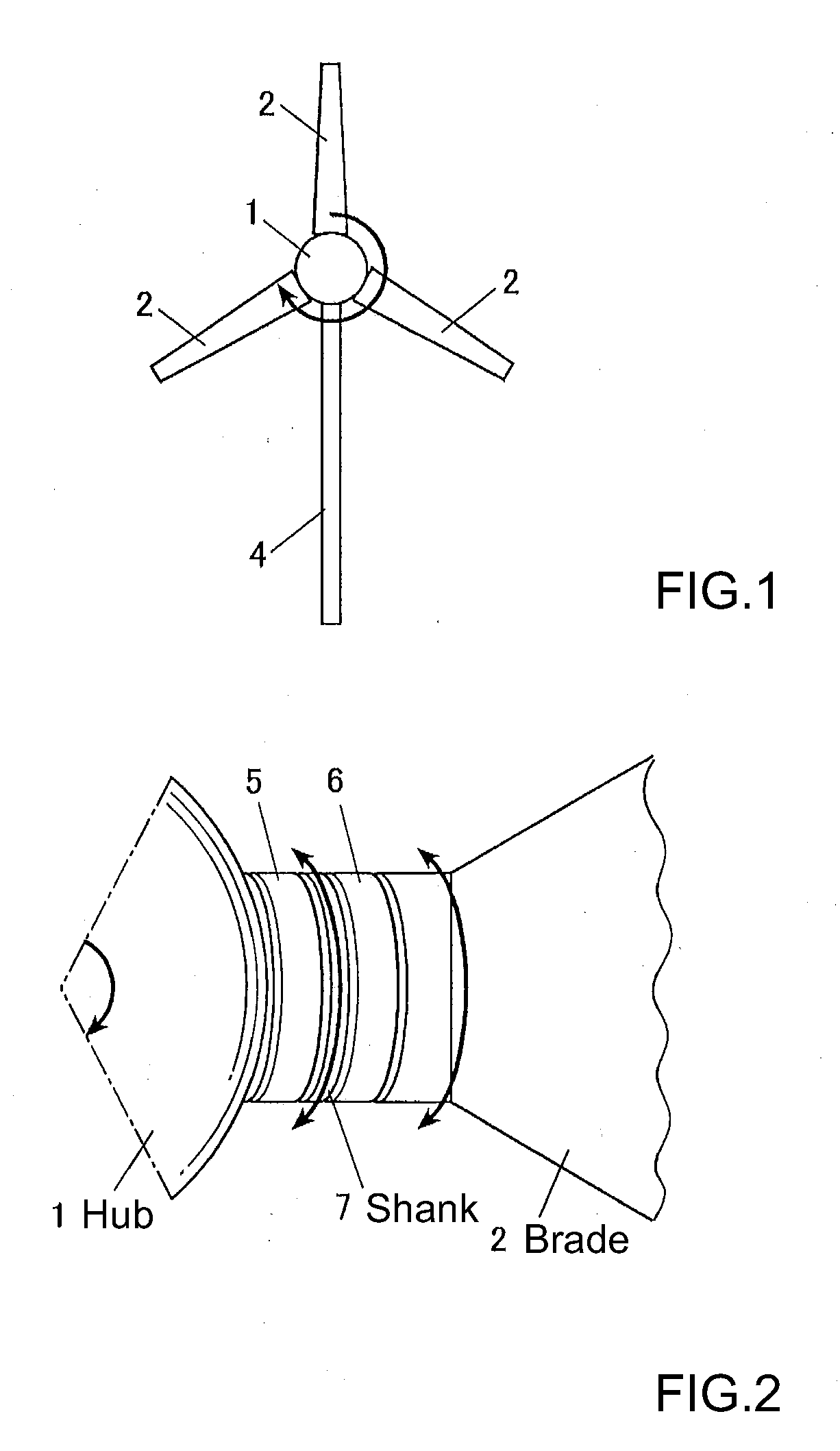
[0049]The horizontal-axis wind turbine of this embodiment as shown in FIG. 1 comprises a rotor having a hub 1 and blades 2. The rotor of this embodiment is a rotor having three blades 2. The number of the blades of the rotor to which the present invention can be applied can be one blade or two or more blades.

[0050]The horizontal-axis wind turbine of this embodiment further comprises a nacelle 3 (see FIG. 10) that supports the rotor by way of a main shaft (not shown in the figure) that is connected to the hub 1 such that it can rotate freely, and a tower 4 that supports the nacelle 3 such that yaw rotation is possible.

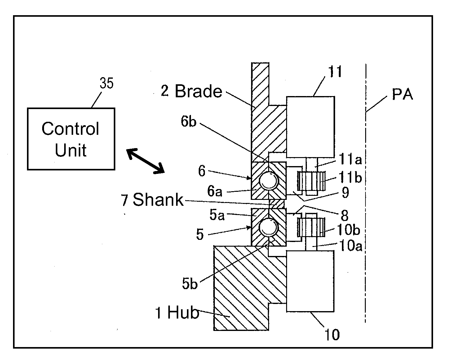
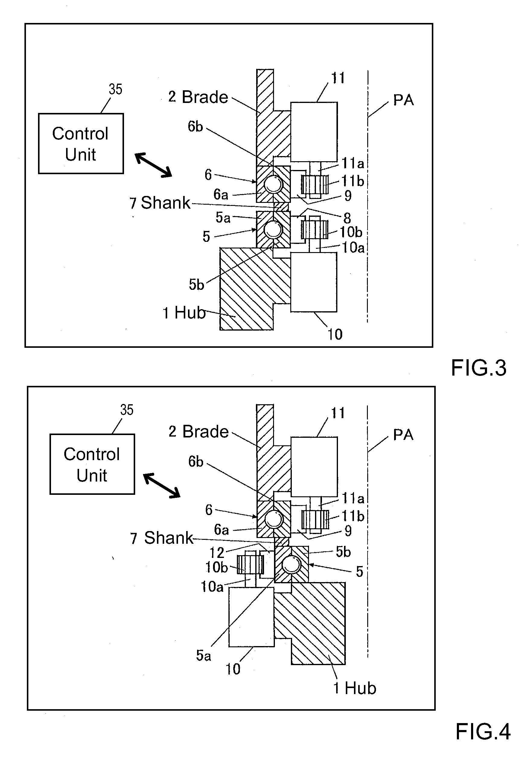
[0051]Next, the pitch drive-control mechanism of this embodiment will be explained.

[0052]As illustrated in FIG. 2 and FIG. 3, an internal ring gear 8...


PUM


Abstract

The object of the invention is to construct a horizontal-axis wind turbine comprising a dual-system pitch drive unit for one blade that is independent up to the transmission mechanism or a dual-system yaw drive unit for one wind turbine nacelle that is independent up to the transmission mechanism, and to provide the dual system with new applicability. The horizontal-axis wind turbine of the present invention has a hub 1 and a blade 2 that are connected by way of an interposed section 5b, 6b, 7 which can freely rotate around the pitch axis of the blade with respect to both the hub and the blade; and further comprises: a hub-side interposed section drive unit 10 that relatively rotates the interposed section with respect to the hub, and a blade-side interposed section drive unit 11 that relatively rotates the blade with respect to the interposed section. The horizontal-axis wind turbine further comprises a hub-side interposed section angle sensor, a blade-side interposed section angle sensor and hub-side blade angle sensor, and is configured to control the pitch angle of the blade with respect to the hub whether controlling both drive units or controlling only one drive unit. Similar connection mechanism and drive and control mechanism is applied to between a tower and a nacelle.

Description

CROSS REFERENCE TO RELATED APPLICATIONS[0001]This application claims priority under 35 U.S.C. 119 based upon Japanese Patent Application No. 2009-124132, filed on May 22, 2009. The entire disclosure of the aforesaid application is incorporated herein by reference.FIELD OF THE INVENTION[0002]The present invention relates to a horizontal-axis wind turbine, and more particularly to pitch drive control and yaw drive control technology.BACKGROUND OF THE INVENTION[0003]As is well known, so-called horizontal-axis wind turbines are widely used in industry such as for wind-generated electricity. A horizontal-axis wind turbine comprises a rotor having one or more blades that are radially attached to a hub, a nacelle that is connected to the hub and supports the axle of the rotor via a main shaft that extends in the horizontal direction, and a tower that is erected in a vertical direction, supports the nacelle so that it has free yaw rotation.[0004]Conventionally, variable pitch type horizonta...

Claims


Application Information

Patent Timeline
IPC IPC(8): B64C11/06B63H1/28
CPCF03D7/0224F05B2270/328F05B2270/329F05B2270/602F03D7/0204F05B2260/79F05B2260/845Y02E10/723Y02E10/72
Inventor YOSHIDA, SHIGEO
Owner HITACHI LTD
Why Eureka
Try Eureka