
Systems and methods for microfluidic crystallization

a microfluidic and crystallization technology, applied in the field of crystallization in microfluidic systems, can solve the problems of reducing the reproducibility of the crystallization process, and increasing the difficulty in obtaining accurate kinetic data

Inactive Publication Date: 2010-11-25
MASSACHUSETTS INST OF TECH
View PDF29 Cites 5 Cited by
  • Summary
  • Abstract
  • Description
  • Claims
  • Application Information

AI Technical Summary

Problems solved by technology

Traditional batch processes may also suffer from poorly controlled mixing of reagents, important in precipitation and antisolvent-driven crystallization.
This may reduce reproducibility of the crystallization process and increase difficulty in obtaining accurate kinetics data.
In addition, batch processes may limit the number of crystallization experiments that may be performed over a given length of time within a particular device.
Moreover, changing process parameters in micro batches may require that the entire apparatus be reconfigured, possibly resulting in an entire batch being wasted at once.

Method used


Image

  • Systems and methods for microfluidic crystallization
  • Systems and methods for microfluidic crystallization
  • Systems and methods for microfluidic crystallization

Examples


example 1

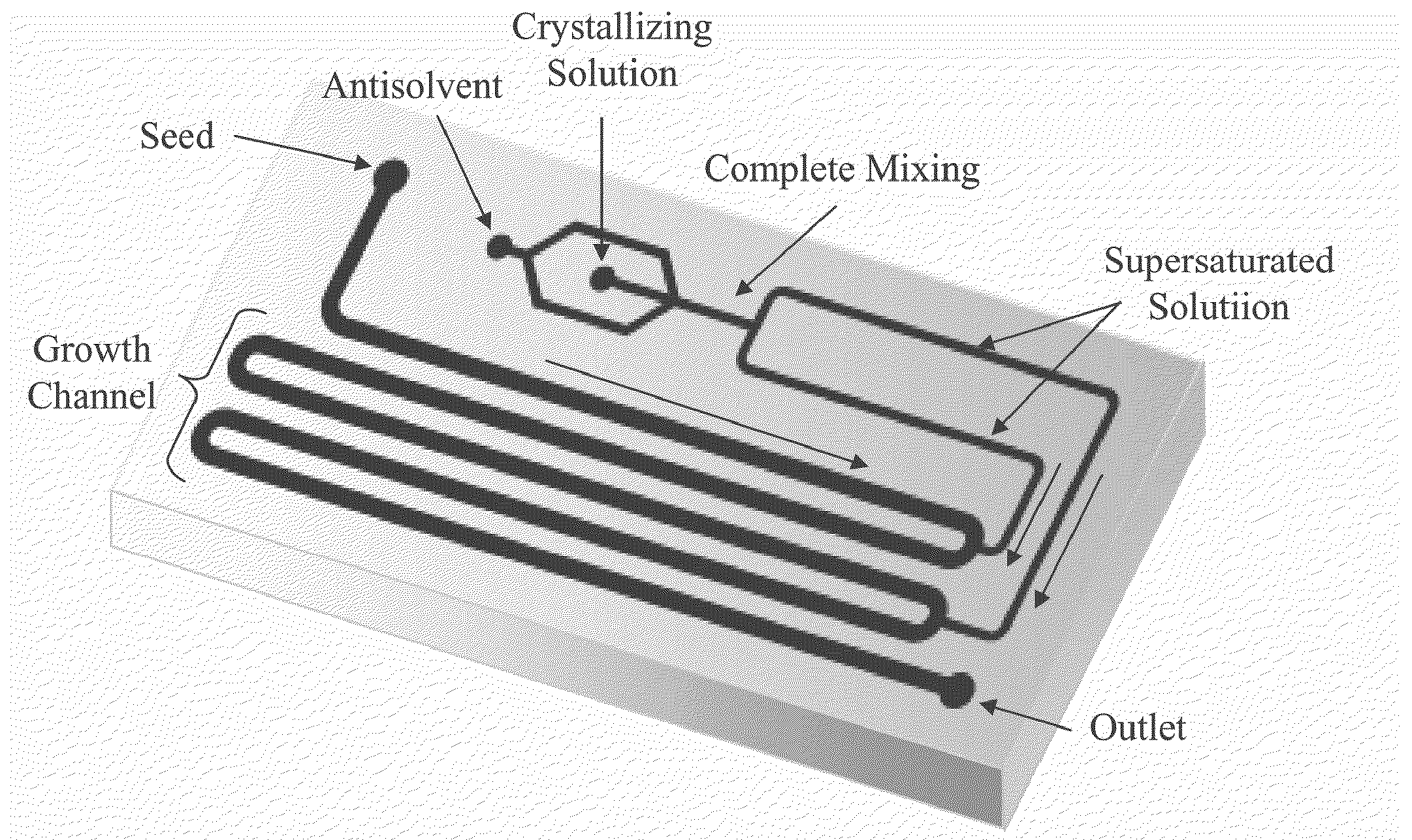
[0071]This example describes crystallization of glycine, according to one set of embodiments. The three most common polymorphs of glycine—gamma, alpha and beta—are shown in FIG. 6. Seeds of each of the three glycine polymorphs were introduced into the reactor in separate experiments, and their growth rates were calculated. In this example, seeded crystallization was used to eliminate uncontrolled nucleation. FIG. 7 includes a schematic illustration of the reactor used in this example. In one inlet, a feed of saturated aqueous glycine seeds was delivered at 10 microliters / min to the microfluidic device at room temperature. Via another inlet, a 40% saturated aqueous glycine solution was fed to the device. In a third inlet, an antisolvent of pure ethanol was fed to the device. The antisolvent and the 40% saturated aqueous glycine solution were mixed on chip to generate a supersaturated solution of glycine. The supersaturated glycine solution was subsequently added to the primary fluidi...

example 2

[0074]In this example, simulations were performed to study the transport of fluid and crystal precursor within a microfluidic channel. FIG. 9 illustrates the fluid velocity profile of a primary fluidic stream mixed with a side-stream. The velocity profile of this aqueous solution was simulated using FEMLAB, a multiphysics modeling and analysis software. FIG. 10 includes calculations of supersaturation as a function of cross-sectional position at various points along the length of the channel. As seen from the plot, substantially uniform supersaturation is achieved 12 mm from the point of mixing. This corresponds to a time of approximately 5 seconds, or about 3.4% of the length of the channel over which growth occurs in this example. The short mixing time was much smaller than the dispersion inherent in the crystal growth process, which is in the order of about 30% for organic crystals, as shown in L. Li, et al., Growth kinetics and mechanim of glycine crystals. Journal of Crystal Gr...


PUM

PropertyMeasurementUnit
sizeaaaaaaaaaa
sizeaaaaaaaaaa
sizeaaaaaaaaaa

Abstract

Systems and methods for crystallization in microfluidic systems are generally described. Many applications require the collection of time-resolved data to determine advantageous conditions for crystallization. The present invention provides tools and related techniques which address this need, as well as a platform for the growth of crystals within microfluidic channels. The systems and methods described herein provide, in one aspect, tools that allow for controlled, stable crystallization of organic materials in microfluidic channels. The invention can interface not only with microfluidic / microscale equipment, but with macroscale equipment to allow for the easy injection of fluids (e.g., fluids containing crystal precursor), extraction of crystals, determination of one or more crystal properties (e.g., crystal size, size distribution among multiple crystals, morphology, etc.), etc.

Description

FIELD OF INVENTION[0001]Systems and methods relating to crystallization in microfluidic systems are generally described.BACKGROUND[0002]Crystallization is the process of forming solid crystals from a precursor such as, for example, a solution, a melt, or a vapor. Traditionally, crystallization has been performed in batch processes that may suffer from non-uniform process conditions such as temperature, important in temperature-driven crystallization, and concentration, important in concentration-driven crystallization. Traditional batch processes may also suffer from poorly controlled mixing of reagents, important in precipitation and antisolvent-driven crystallization. Consequently, crystal growth can vary across the reactors, giving rise to polydisperse crystal size distribution (CSD). This may reduce reproducibility of the crystallization process and increase difficulty in obtaining accurate kinetics data. In addition, batch processes may limit the number of crystallization exper...

Claims


Application Information

Patent Timeline
Patent Type & Authority Applications(United States)
IPC IPC(8): C07C229/08G01N15/00C07C229/06
CPCC07C227/42C07C229/08
Inventor SULTANA, MAHMOODAJENSEN, KLAVS F.
Owner MASSACHUSETTS INST OF TECH
Learn More