
Flow elements for use with flexible spinal needles, needle assemblies and methods therefor

a flow element and flexible needle technology, applied in the field of medical devices, can solve the problems of unacceptably high incidence of post-dural puncture headaches (“pdph”), severe limitation of the usefulness of continuous spinal techniques, and difficulty in handling catheters, so as to prevent or at least minimize the extent of flow occlusion, improve the performance of flexible needles, and minimize the incidence of post-dural puncture headaches

Active Publication Date: 2010-11-25
CUSTOM MEDICAL APPL
View PDF23 Cites 2 Cited by
  • Summary
  • Abstract
  • Description
  • Claims
  • Application Information

AI Technical Summary

Benefits of technology

"The patent describes a flexible needle assembly for minimizing flow occlusion in a spinal needle. The assembly includes a support needle, a flexible needle, and a central stylet. The flexible needle has a flow element with an internal flow path for conducting fluid through the needle. The assembly also includes an anti-restriction member to prevent kinking and flow occlusion. The use of the flexible needle assembly reduces the risk of neurological damage and allows for easier and faster flow of fluid. The assembly is simple, safe, and can be used in various medical procedures."

Problems solved by technology

Unfortunately, technical problems have severely limited the usefulness of continuous spinal techniques.
Until recently, the standard technique of inserting the spinal catheter through the spinal needle, coupled with the difficulty of manufacturing truly small needles and catheters, has meant large needles and catheters were required, resulting in an unacceptably high incidence of post-dural puncture headaches (“PDPH”).
Unfortunately, these catheters proved difficult to handle, difficult to make, expensive, and, more ominously, associated with several reports of neurologic damage (i.e., cauda equina syndrome).
The FDA's decision to recall and ban the marketing of microspinal catheters for CSA in the U.S., and its requirement that any new device for CSA be subjected to an extremely stringent pre-market approval process, has resulted in a freeze on the development of these products, at least in the United States.
Nevertheless, the injection of local anesthetics for the establishment of surgical anesthesia is not the only use to which such devices might beneficially be put.
Installing a conventional catheter generally requires various cumbersome steps involving threading long, very thin catheters through a spinal needle.
Simply threading a catheter into the end of a spinal needle can be so difficult that some manufacturers include a “threading aid” as part of their kit.
Once threaded, a degree of uncertainty exists for the clinician about how far to insert the catheter.
Also, a risk exists that a piece of the catheter might be sheared off by the needle if the catheter were to be pulled back during the threading operation.
Furthermore, removing the spinal needle while holding the catheter in position can be a challenge.
Additionally, attaching a hub / injection adapter to the naked end of the 28 g or 32 g catheter can be even more of a challenge.
In short, the conventional spinal catheter threading operation requires considerable time and effort on the part of a clinician.
One problem of Sprotte and Whitacre non-cutting spinal needles is that the injection orifice is on the side of the needle.
Another problem with Sprotte and Whitacre spinal needles is that the smooth curved tip profile provides no definitive feedback signal or “click” when the dura is punctured.
Such lack of feedback contributes to uncertainty of catheter tip placement.

Method used


Image

  • Flow elements for use with flexible spinal needles, needle assemblies and methods therefor
  • Flow elements for use with flexible spinal needles, needle assemblies and methods therefor
  • Flow elements for use with flexible spinal needles, needle assemblies and methods therefor

Examples


Embodiment Construction

[0045]The illustrations presented herein are, in some instances, not actual views of any particular flow element, flexible needle assembly or other feature of a flexible spinal needle assembly, but are merely idealized representation that are employed to describe the invention. Additionally, elements common between figures may retain the same numerical designation.

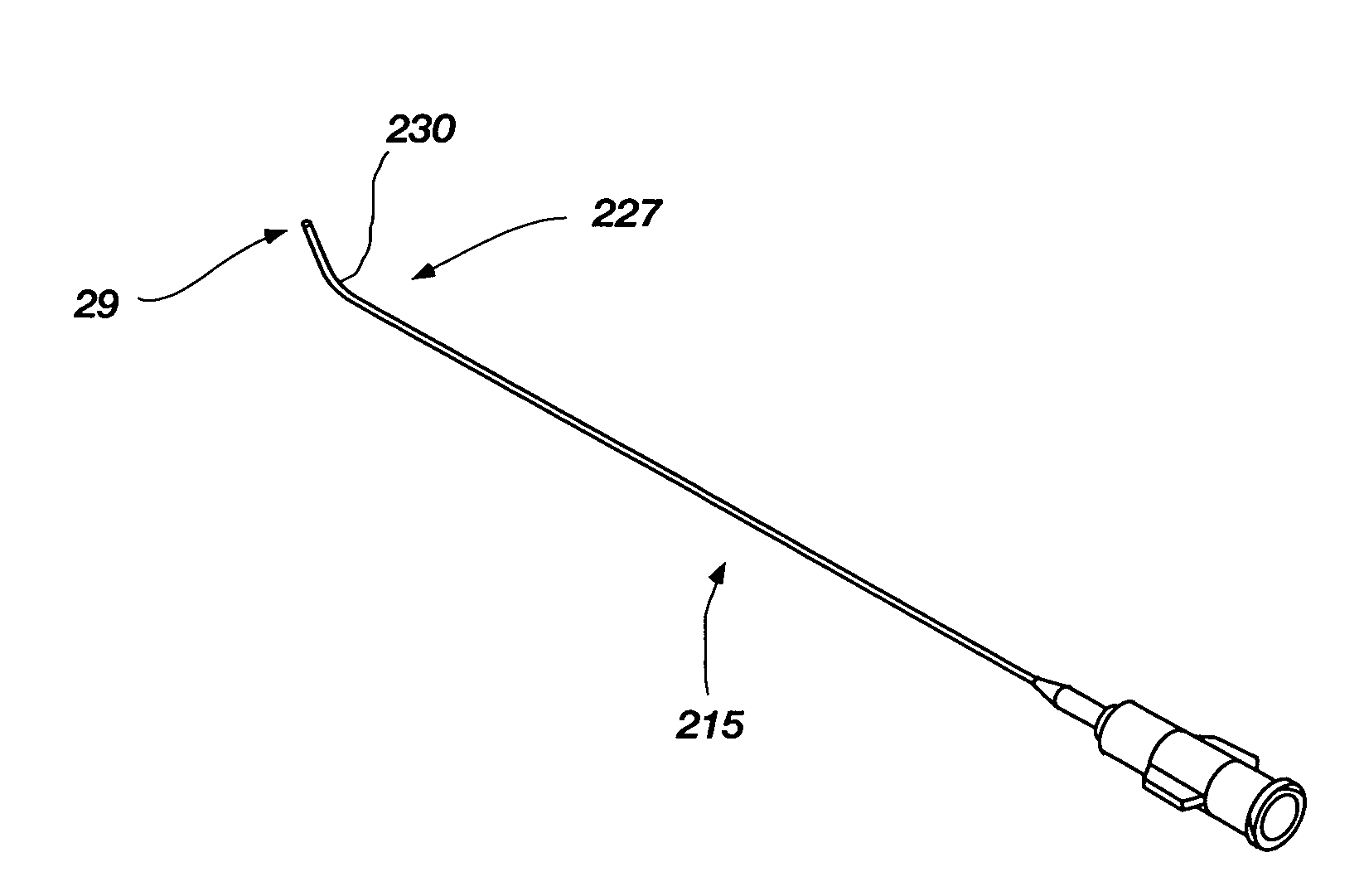
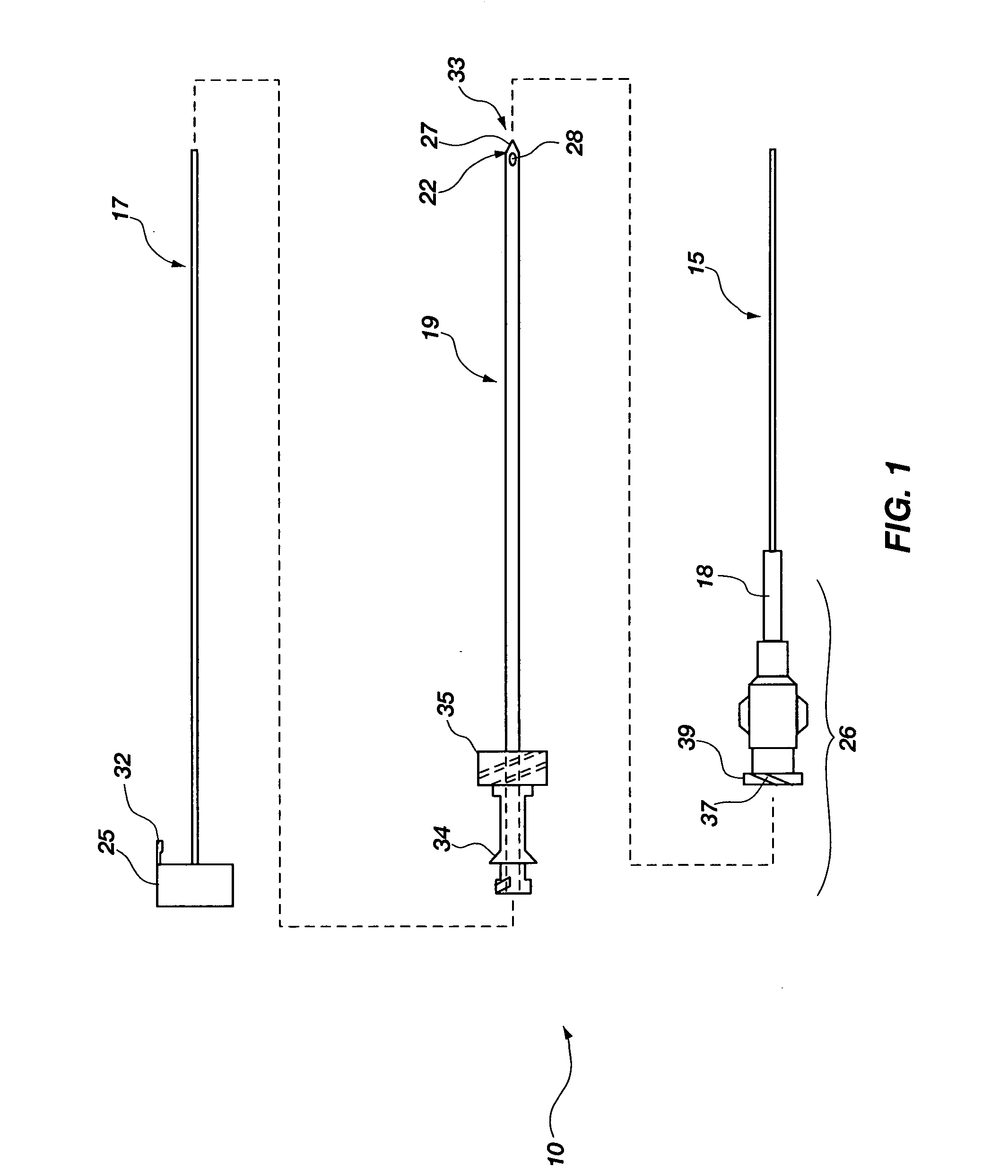
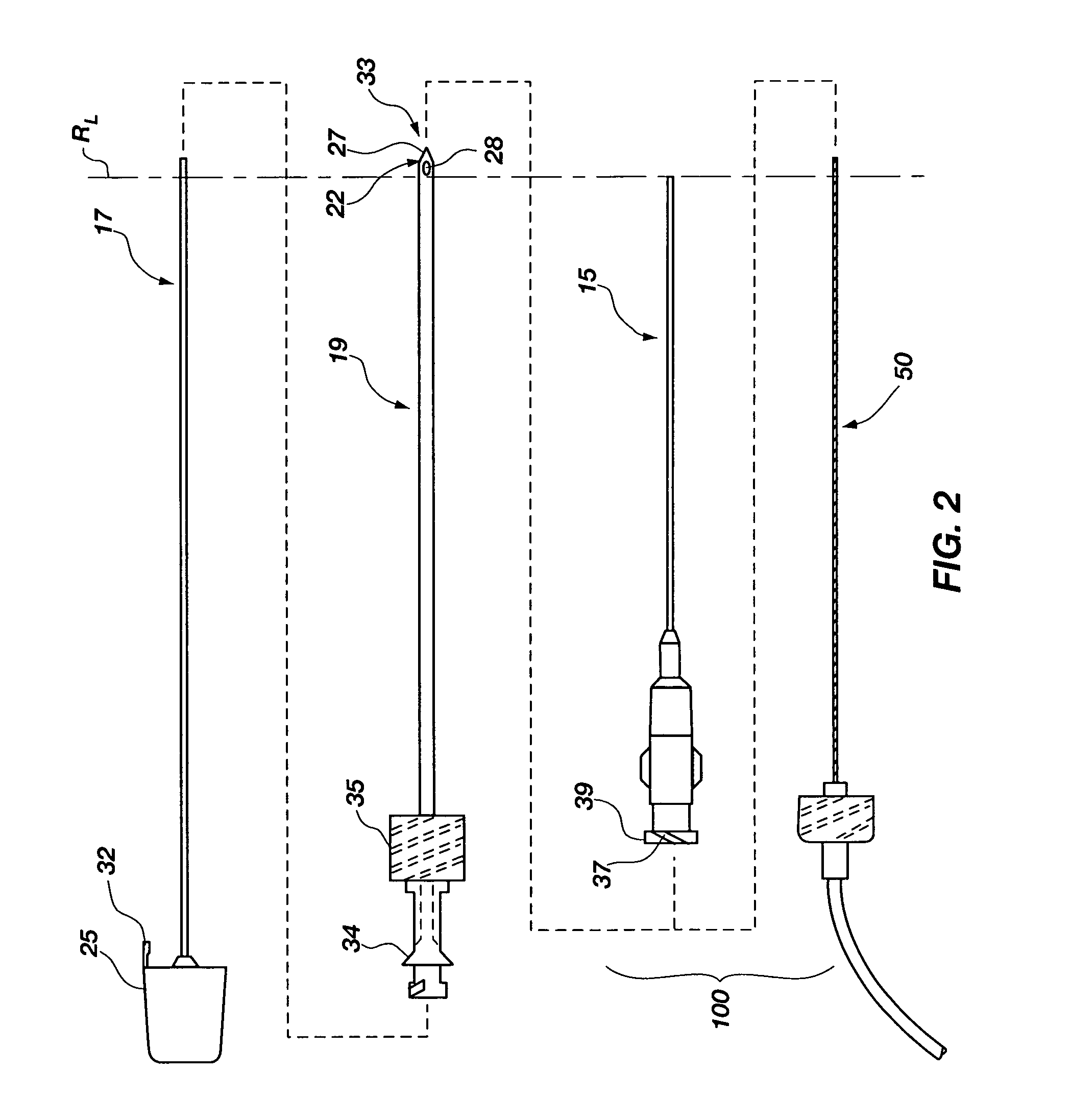
[0046]Generally, the flow element may be advantageously used with an integrated spinal needle or flexible needle assembly 10 (much like an intravenous needle and catheter mounted therein) as shown in FIG. 1, however, in which the flexible needle 15 is releasably mounted on the outside of a support needle 19. The flexible needle 15 is configured for uses with embodiments of the invention as will be further described below, and is also configured for placement on the outside of the support needle 19 that provides a number of advantages which are first described before turning to the embodiments of the invention. First, this ...


PUM


Abstract

A flow element for use with flexible needles and flexible needle assemblies to minimize flow occlusion within a flexible needle is provided. The flow element is particularly suited for uses with a flexible needle for minimizing incidence of post-dural puncture headache. The flow element includes a body having an internal flow path for conducting a fluid through a flexible needle, and an anti-restriction member. The anti-restriction member includes an elongated body, a proximal end coupled to the body within the internal flow path, and a distal end for disposing at least a portion of the elongated body within a flexible needle. A flexible spinal needle assembly for minimizing flow occlusion through an internal flow path of a flexible needle by unintended kinking that is potentially caused by ligament or muscle layer movements is also provided. In other embodiments, a flexible spinal needle assembly, a flexible spinal needle assembly kit, a method for installing a flexible spinal needle assembly, and a process for producing a flow element are provided.

Description

CROSS-REFERENCE TO RELATED APPLICATION[0001]This application is a divisional of U.S. patent application Ser. No. 12 / 009,349, filed Jan. 17, 2008, pending, the contents of which are hereby incorporated herein by this reference in its entirety.FIELD OF THE INVENTION[0002]This invention relates generally to medical devices, and particularly to structures for fluid occlusion prevention in medical needles. It is particularly directed to a flow element for use with flexible needles and flexible spinal needle assemblies, including methods therefor.BACKGROUND[0003]The advantages of continuous spinal anesthesia have long been appreciated by anesthesiologists. Unlike conventional single-shot techniques, continuous spinal anesthesia (“CSA”) with an indwelling catheter allows anesthesia of unlimited duration and the ability to carefully control the level of the block by administering repeated small, incremental doses of anesthetic. As compared to continuous epidural anesthesia, which has become...

Claims


Application Information

Patent Timeline
Patent Type & Authority Applications(United States)
IPC IPC(8): A61M5/32
CPCA61M25/0606A61B17/3401
Inventor RACZ, N. SANDOR
Owner CUSTOM MEDICAL APPL
Learn More