Airflow-cooling apparatus for a ceiling air-conditioning circulation machine

a circulation machine and airflow cooling technology, which is applied in the direction of domestic cooling apparatus, ventilation systems, heating types, etc., can solve the problems of inability to reduce the temperature of air, and inability to achieve the cooling effect of simple inflow/outflow action, so as to achieve the optimal convection of indoor air, reduce the temperature thereof, and reduce the effect of indoor temperatur

Inactive Publication Date: 2010-12-02
CHEN YUNG HUA
View PDF3 Cites 20 Cited by
  • Summary
  • Abstract
  • Description
  • Claims
  • Application Information

AI Technical Summary

Benefits of technology

[0006]An object of the invention is to provide an airflow-cooling apparatus of a ceiling air-conditioning circulation machine that permits an optimal convection of the indoor air. During the convection, the drawn air can be cooled for reducing the temperature thereof. In this way, the indoor temperature can be reduced by means of the continuous circulation flow. Thus, the energy consumption and the carbon release can be reduced.
[0007]Another object of the invention is to provide an airflow-cooling apparatus of a ceiling air-conditioning circulation machine whose air outflow / inflow channels are concentrically arranged in a conic shape, thereby achieving a 360° thorough inflow effect.

Problems solved by technology

However, the conventional fan or circulation machine is employed only to draw the indoor air from the bottom thereof and to deliver it by a vane wheel indoors.
However, it is pity that the convection air can't be cooled for reducing the indoor temperature.
The simple inflow / outflow action can't achieve the cooling effect.
Therefore, it is not easy to reduce the temperature of the air.

Method used


Image

  • Airflow-cooling apparatus for a ceiling air-conditioning circulation machine
  • Airflow-cooling apparatus for a ceiling air-conditioning circulation machine
  • Airflow-cooling apparatus for a ceiling air-conditioning circulation machine

Examples


Embodiment Construction

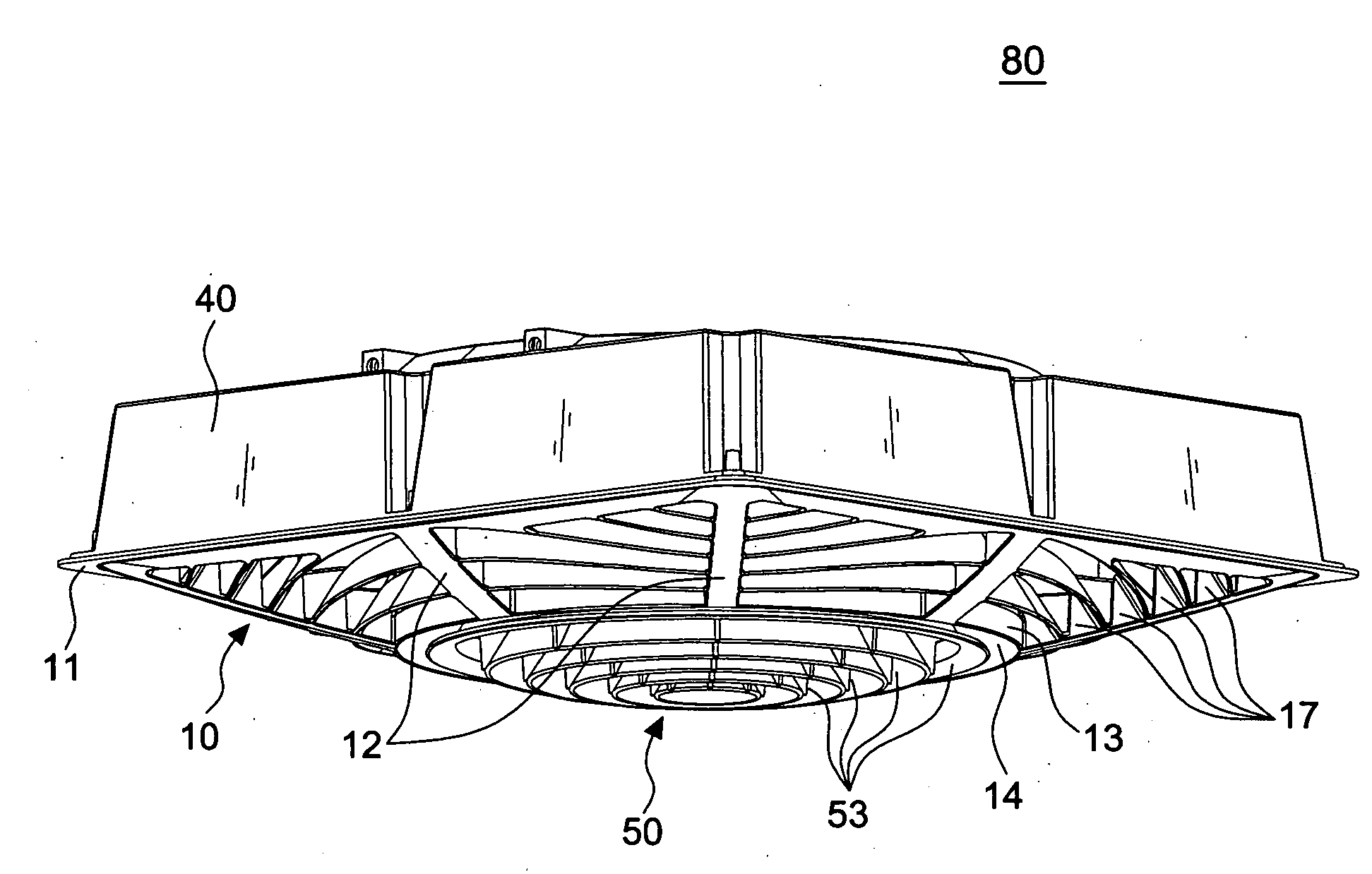
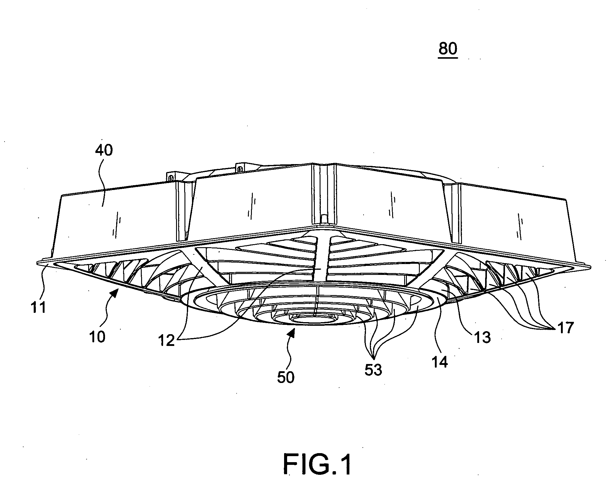
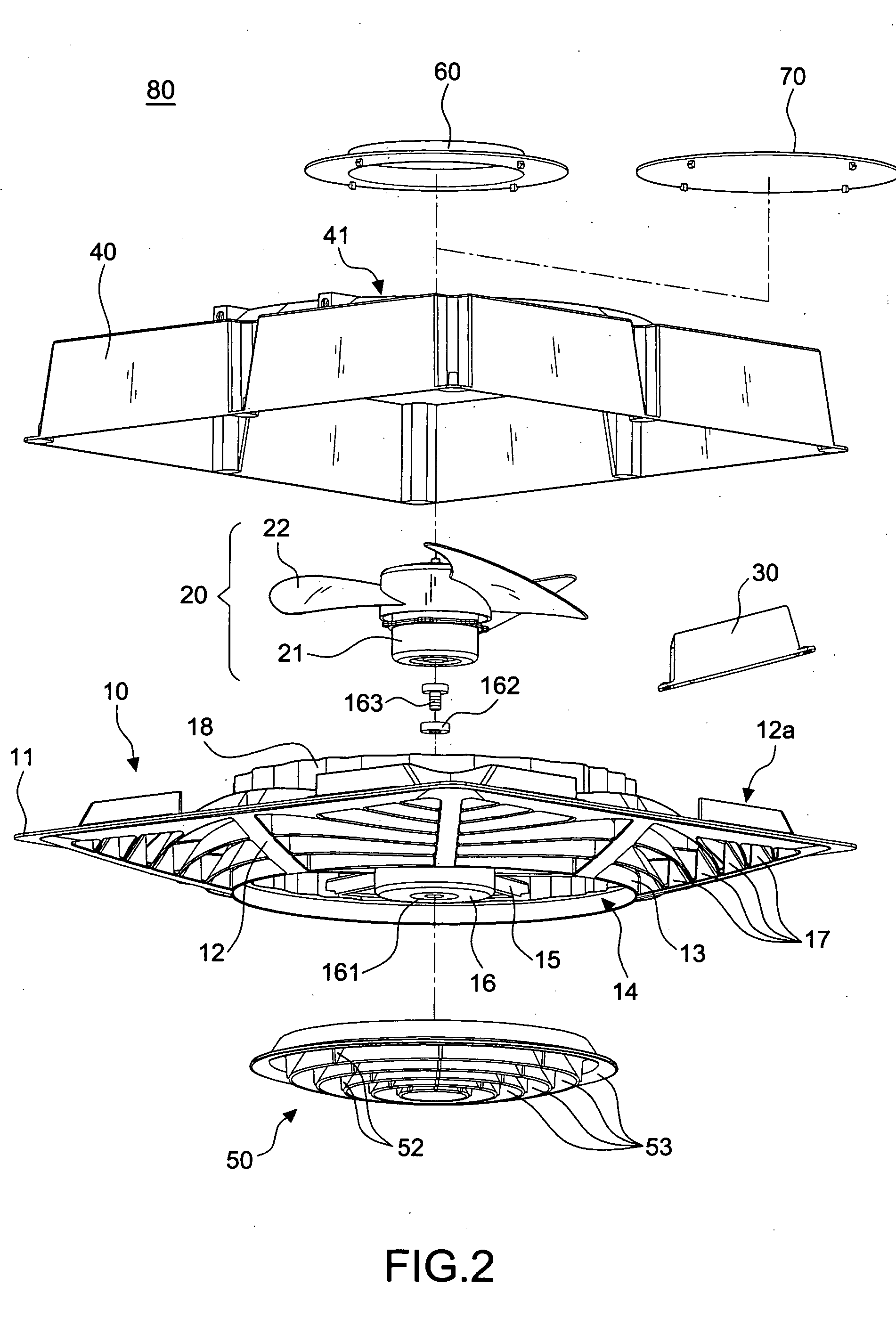
[0017]First of all, referring to FIGS. 1 through 8, an airflow-cooling apparatus of a ceiling air-conditioning circulation machine in accordance with the invention includes a base frame 10, a fan 20, a signal-receiving controller 30, and a cover cap 40.

[0018]As shown in FIG. 3, the base frame 10 includes a rectangular positioning frame 11 at the rim thereof for installing within a grid frame (not shown) of a light steel frame. A plurality of radial supports 12 are extended from the periphery of the positioning frame 11 inwards (see FIGS. 1 and 2). A circular frame 13 is positioned at the center of the base frame 10. The rim of the circular frame 13 is attached to the radial supports 12. In other words, the circular frame 13 is supported and fixed by the radial supports 12. Moreover, a fan base 16 is positioned within the circular hole 14 of the circular frame 13 and supported by a plurality of ribs 15. A plurality of conic and ring-shaped air outflow / inflow channels 17 are concentri...


PUM


Abstract

An airflow-cooling apparatus of a ceiling air-conditioning circulation machine, and more particularly a structure permitting a smooth flow of the indoor air, wherein the drawn current of air passes through a cooling apparatus and then is guided indoors for reducing the temperature. Thus, the energy consumption and the carbon release can be reduced. According to the invention, a base frame includes a base frame having a rectangular positioning frame at the rim thereof. A plurality of radial supports are extended from the periphery of the positioning frame inwards. A circular frame is positioned at the center of the base frame. The rim of the circular frame is attached to the radial supports. A fan base is positioned within the circular hole of the circular frame and supported by a plurality of ribs. A plurality of conic and ring-shaped air outflow / inflow channels are concentrically and outwardly interposed between the circular frame and the positioning frame. Moreover, a wave-shaped cooling ring frame is disposed on the circular frame. In this way, a wavy flow is ensured when the indoor air pass through the conic air outflow / inflow channels into a cooling ring frame. Thus, the structure according to the invention achieves the flowing and cooling effect.

Description

BACKGROUND OF THE INVENTION[0001]1. Field of the Invention[0002]The invention relates to an airflow-cooling apparatus of a ceiling air-conditioning circulation machine, and more particularly to an apparatus that permits an optimal flow of the indoor air and a considerable reduction of temperature.[0003]2. Description of the Related Art[0004]When offices or factories are interiorly decorated, the ceiling is often made by light steel frame in a grid shape. Thereafter, the ceiling is placed in the grid frame. This kind of the construction way is simple and has low cost. Thus, it is widely used.[0005]In order to enhance the convection of the indoor air, an air-conditioning circulation machine or a fan is often placed into the grid frame. Such a structure is disclosed in TW M251939, M322475, etc. However, the conventional fan or circulation machine is employed only to draw the indoor air from the bottom thereof and to deliver it by a vane wheel indoors. However, it is pity that the conve...

Claims


Application Information

Patent Timeline
Patent Type & Authority Applications(United States)
IPC IPC(8): F25B49/00F25D23/00F25D17/06
CPCF24F2221/14F24F7/025
Inventor CHEN, YUNG-HUA
Owner CHEN YUNG HUA
Why Eureka
Try Eureka