Air Filter And Air Filter Assembly For Vacuum Cleaner With The Air Filter

Inactive Publication Date: 2010-12-02
JAPAN GORE TEX INC
View PDF10 Cites 10 Cited by
  • Summary
  • Abstract
  • Description
  • Claims
  • Application Information

AI Technical Summary

Benefits of technology

[0014]According to the present invention, the average fiber diameter in the front surface of the permeable support material on which the ePTFE membrane is laminated is caused to be smaller than the average fiber diameter in the back surface of the permeable support material, thereby smoothing the front surface of the permeable support material. Thus, the number of contact points between the ePTFE membrane and the permeable support material increases, and the adhesiveness therebetween

Problems solved by technology

However, as described above, pressure and vibration are periodically applied to the air fi

Method used


Image

  • Air Filter And Air Filter Assembly For Vacuum Cleaner With The Air Filter
  • Air Filter And Air Filter Assembly For Vacuum Cleaner With The Air Filter
  • Air Filter And Air Filter Assembly For Vacuum Cleaner With The Air Filter

Examples


Example

EXAMPLE

[0077]The following will describe the present invention more specifically by averages of examples. However, the present invention is not limited by the following examples, it is naturally possible to practice the present invention with appropriate modifications as long as they conform to the effect in the descriptions above and below, and these modifications are included in the technological scope of the present invention.

Example

Example 1

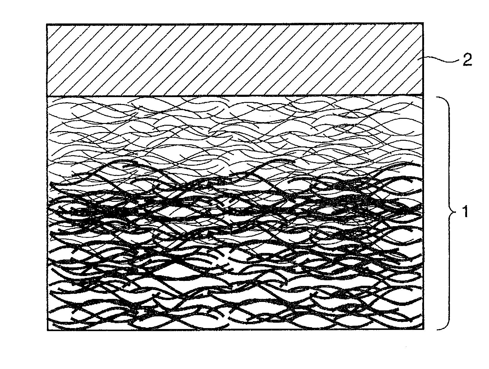
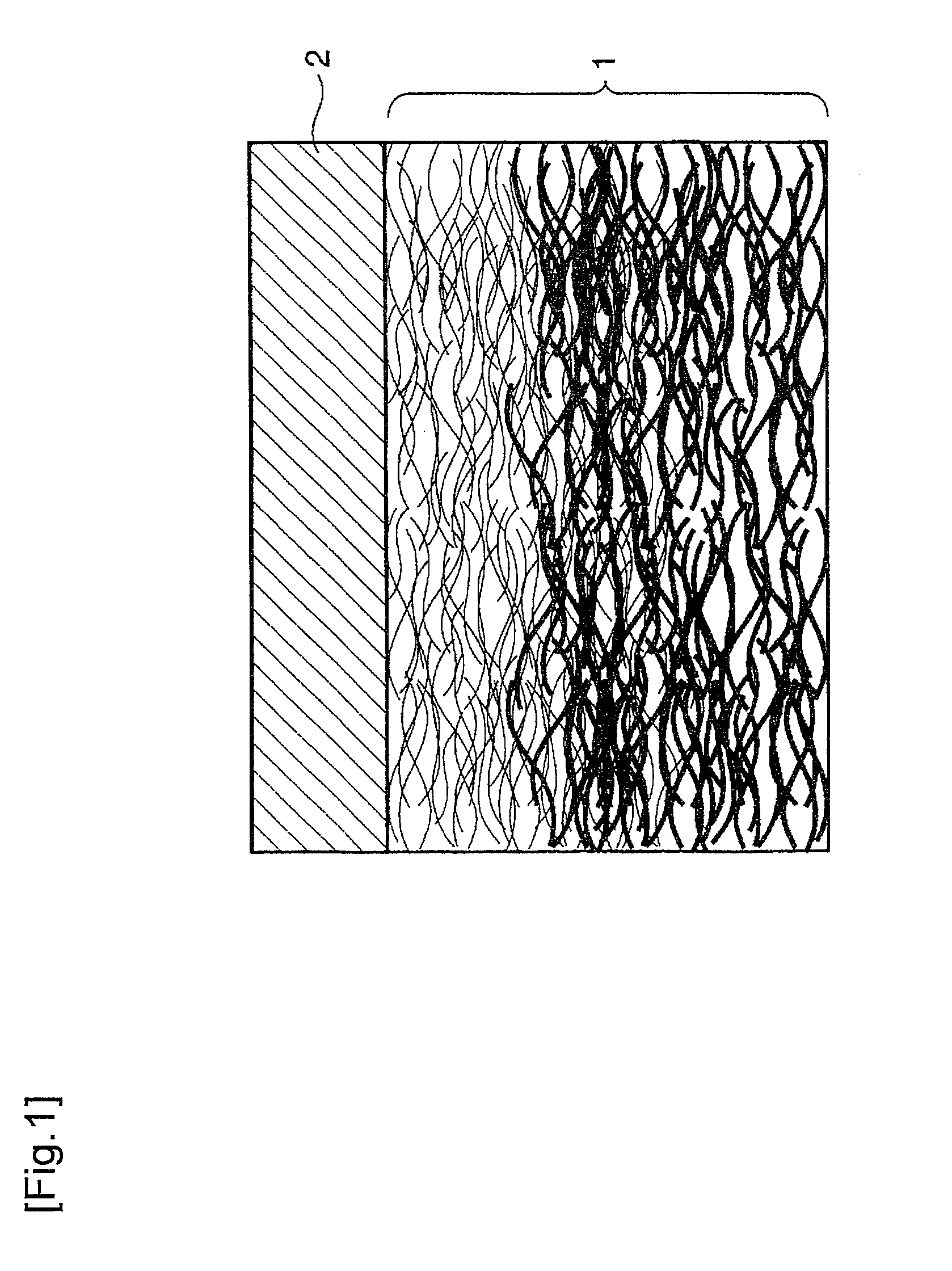
[0078]A permeable support material 1 having a mass per unit area of 100 g / m2 was produced by using a fiber having a dtex value of 2.2 as a material of the fiber sheet 6a, and using a fiber having a dtex value of 16 as a material of the fiber sheet 6b. The fibers used are polyester fibers each having a core-in-sheath structure (Melty, manufactured by Unitika Fibers Ltd.). The lower the dtex value is, the smaller the average fiber diameter is.

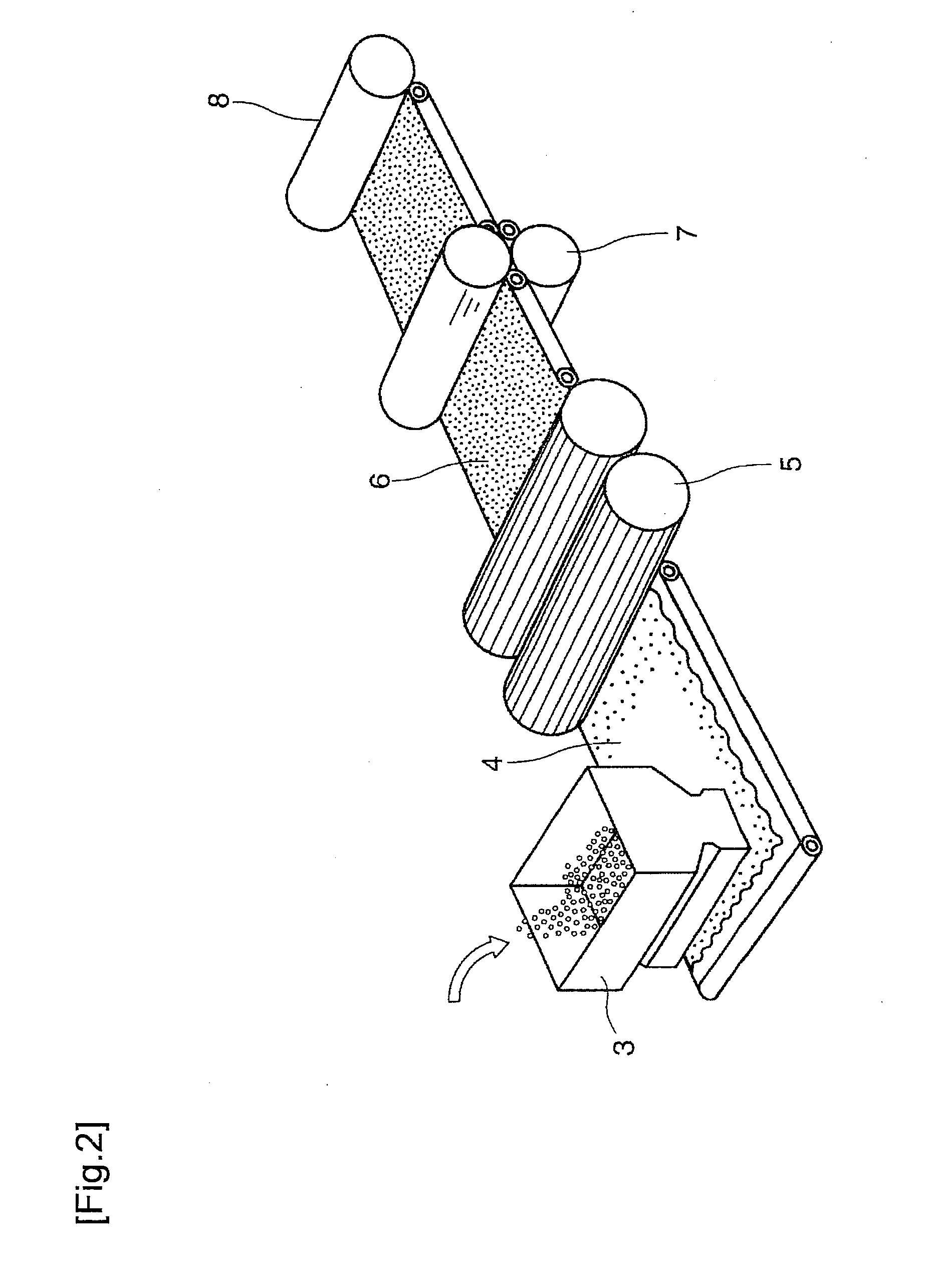
[0079]Specifically, as shown in FIG. 3, two carding machines 5a and 5b were used, and a webbed fiber sheet 6a was produced by the carding machine 5a, and a webbed fiber sheet 6b was produced by the carding machine 5b. These sheets were stacked on each other, and the fibers thereof were entangled with each other by a water jet. Then, coloring, water-repellent treatment, antibacterial treatment, and fungiproofing treatment were conducted by a coating method.

[0080]As the ePTFE membrane 2, an ePTFE membrane (S2-A10012M, manufactured by Japan...

Example

Example 2

[0085]A permeable support material 1 having a mass per unit area of 100 g / m2 was produced by using a fiber having a dtex value of 4.4 as a material of the fiber sheet 6a, and using a fiber having a dtex value of 16 as a material of the fiber sheet 6b. The fibers used are polyester fibers each having a core-in-sheath structure (Melty, manufactured by Unitika Ltd.).

[0086]Similarly as in Example 1, two carding machines 5a and 5b were used, and a webbed fiber sheet 6a was produced by the carding machine 5a, and a webbed fiber sheet 6b was produced by the carding machine 5b. These sheets were stacked on each other, and the fibers thereof were entangled with each other by a water jet. Then, coloring, water-repellent treatment, antibacterial treatment, and fungiproofing treatment were conducted by a coating method.

[0087]As the ePTFE membrane 2, the same one was used as in Example 1. The film was fusion-bonded with the above permeable support material 1 by heat and pressure, to pro...


PUM

PropertyMeasurementUnit
Diameteraaaaaaaaaa
Permeabilityaaaaaaaaaa

Abstract

The invention aims at providing an air filter which is improved in the tight adhesion between an ePTFE membrane and a permeable support material without impairing the mechanical strength and permeability of the support material. An air filter produced by laminating a permeable support material (1) having a region wherein fibers different in fiber diameter are entangled and a porous polytetrafluoroethylene membrane (2), wherein the mean fiber diameter of the membrane-side face of the support material (1) is smaller than that of the back of the support material (1).

Description

TECHNICAL FIELD[0001]The present invention relates to an air filter, and, for example, to a material of an air filter used mainly for removing foreign matter in a cleaner and the like.BACKGROUND ART[0002]Recently, a porous polytetrafluoroethylene membrane (hereinafter, referred to as “ePTFE membrane”, and note that, in the following description concerning Patent Documents 1 and 2, the terms are ones used in these documents) is used as a filter material of an air filter for use in a cleaner such as a dust collector and an air cleaner. This is because: the ePTFE membrane has excellent pressure loss characteristic and collection efficiency; and when the air filter is clogged due to foreign matter such as dust and dirt, the air filter allows the foreign matter to be easily removed therefrom by shaking the air filter, or the like.[0003]Further, an ePTFE membrane that is very thin and includes a relatively small number of nodes and long fibrils, is used in order to achieve both a low pres...

Claims


Application Information

Patent Timeline
IPC IPC(8): B01D71/36B01D69/10B01D53/22A47L9/10A47L9/12B01D39/16B32B5/24B32B27/30D04H1/492
CPCA47L9/14B01D39/163B01D39/1692D04H13/002B01D2239/0668B32B5/14B32B27/12B01D2239/0654B32B5/022B32B5/024B32B5/028B32B5/06B32B5/08B32B5/145B32B5/22B32B5/26B32B5/30B32B27/322B32B2262/0253B32B2262/0261B32B2262/0276B32B2262/12B32B2264/0257B32B2307/50B32B2307/514B32B2307/724B32B2509/00D04H1/4374D04H1/485D04H1/492D04H1/498
Inventor YAMAKAWA, KEIICHI
Owner JAPAN GORE TEX INC
Why Eureka
Try Eureka