Method for Eliminating Spikes of Mercury Emissions

a mercury emission and emission reduction technology, applied in waste heat treatment, special form destructive distillation, coking carbonaceous materials, etc., can solve the problems of large increase in emissions of several of these compounds, and achieve the effects of reducing emissions, reducing variability in emissions, and reducing emissions

Inactive Publication Date: 2010-12-02
F L SMIDTH & CO AS
View PDF4 Cites 18 Cited by
  • Summary
  • Abstract
  • Description
  • Claims
  • Application Information

AI Technical Summary

Benefits of technology

[0003]This invention is a method of reducing the emission levels, including reducing variability in emissions, of mercury and other contaminants from mineral processing systems such as cement or mineral kiln systems during mill stoppages.
[0004]The invention comprises a method and system for the reduction of mercury emissions from an industrial plant utilizing a cement or lime kiln that has a high level of mercury emissions during specific operating conditions. The invention eliminates or significantly reduces a large spike in mercury emissions typically seen in cement kiln systems when the in-line raw mill is shut-down and all preheater gases are vented to the stack directly. The invention treats the preheater gases prior to dedusting and venting by cooling the gases to at least near the condensation temperature (it being understood that when a sorbent is employed mercury and other compounds may absorb at temperatures slightly above—that is, up to about 25° above—their condensation temperature) of certain contaminants, particularly mercury compounds, and absorbing such contaminants on a sorbent either added to the cooling step and / or in the form of the dust exiting the preheater system. The sorbent may be recycled to enhance the capture of mercury. All or some of the recirculated sorbent may be removed and disposed of in order to reduce the overall emissions of mercury in addition to eliminating the spike in emissions.

Problems solved by technology

In studies of operating plants, it has become apparent that a large increase in emissions of several of these compounds occurs within a short period of time following the stoppage of milling operations.

Method used


Image

  • Method for Eliminating Spikes of Mercury Emissions
  • Method for Eliminating Spikes of Mercury Emissions
  • Method for Eliminating Spikes of Mercury Emissions

Examples


second embodiment

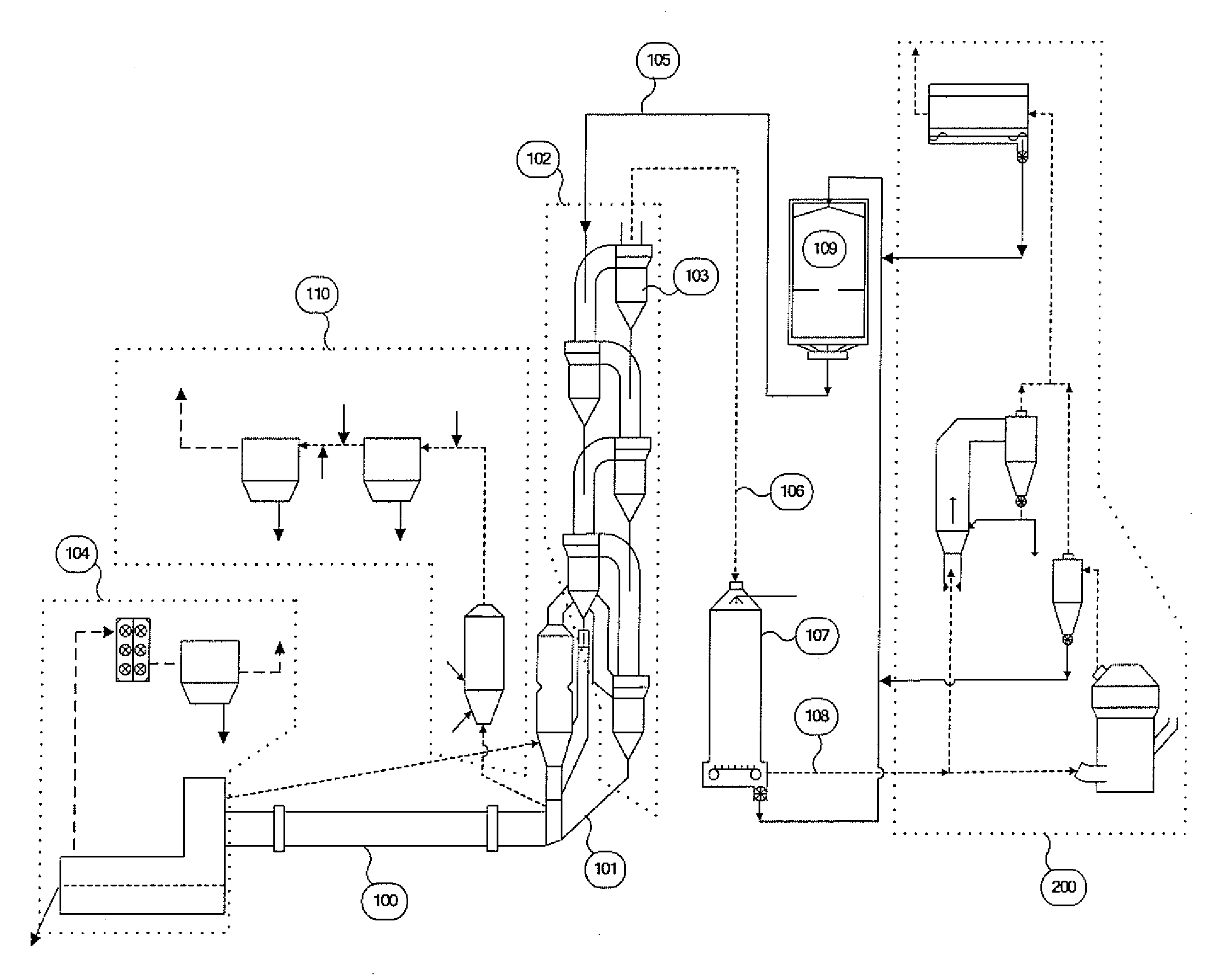
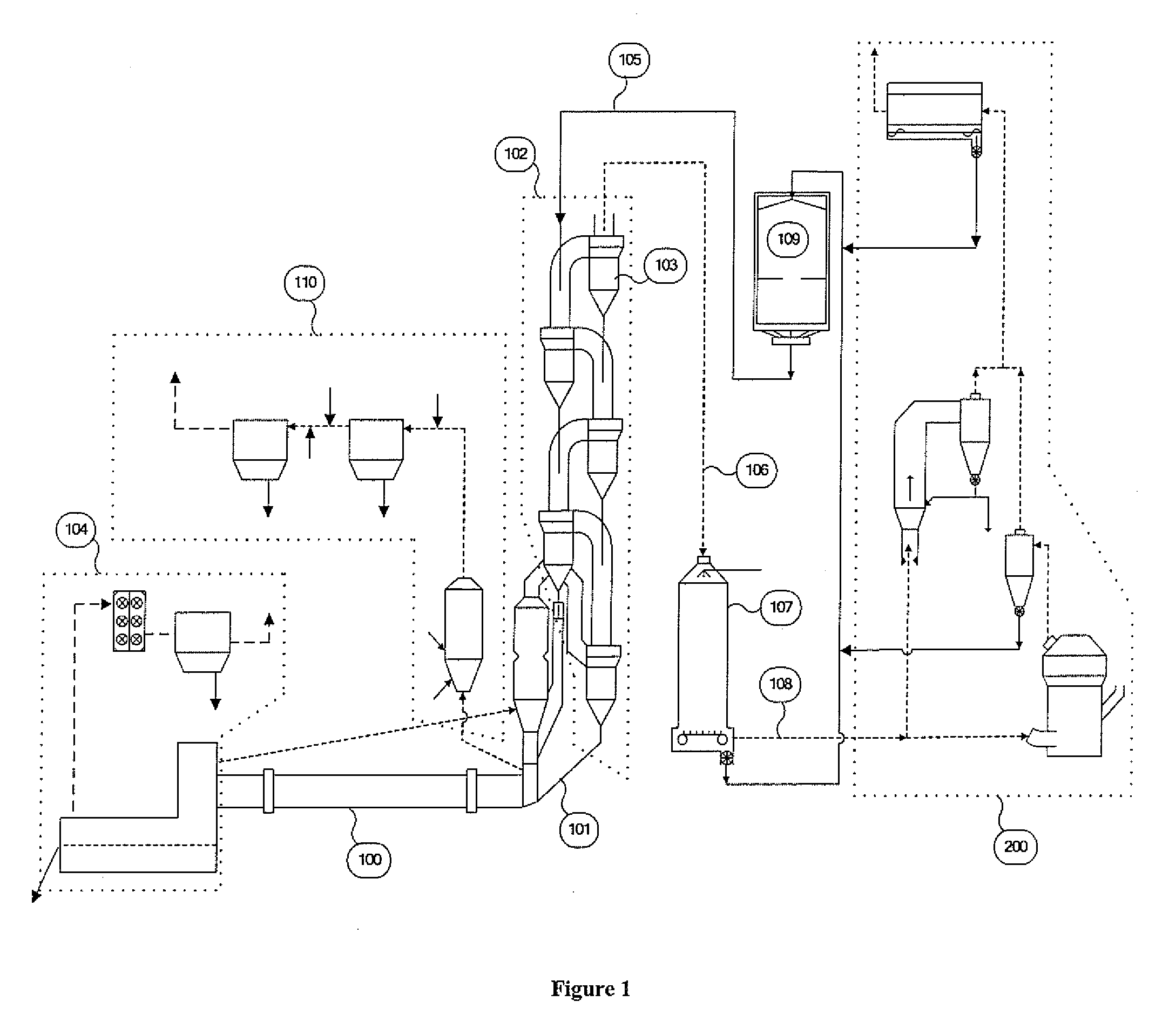
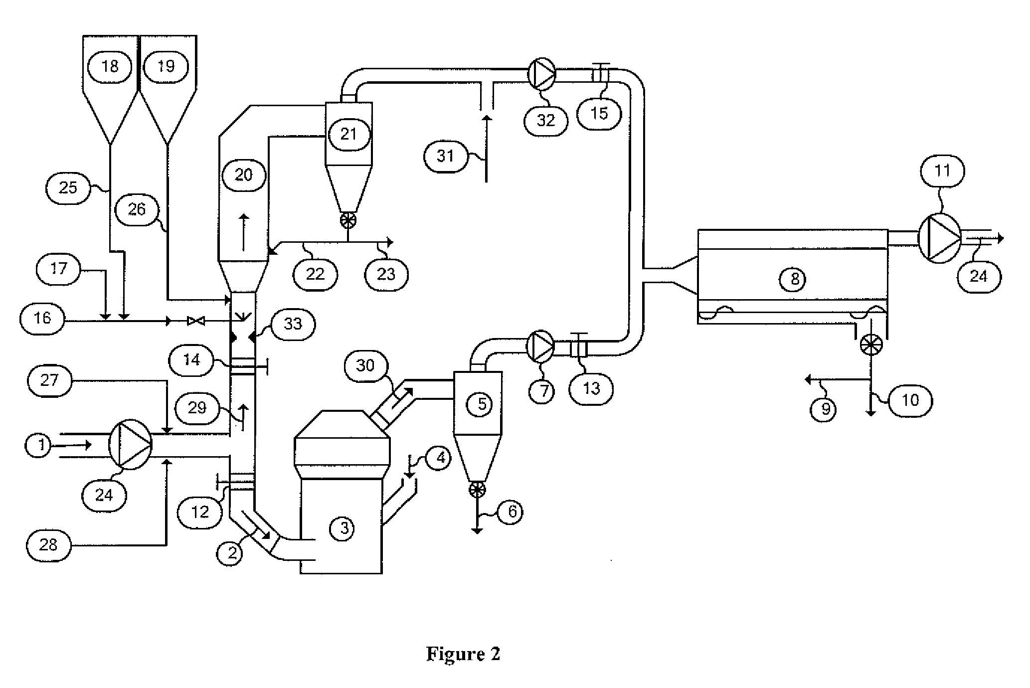
[0033]FIG. 3 shows the present invention which may be utilized depending on the specifications of the particular plant in which the invention is being applied. The embodiment of FIG. 3 is substantially equivalent to the embodiment of FIG. 2, with the notable exception that the off gases, which contain fine product and exhaust gases, from both mill 3 and GSA 20 are directed to the same separation cyclone (or series of cyclones) 21 in which the coarse fraction of the product is collected and conveyed via conduit 6 (or a series of conduits) to other locations in the plant for storage, blending and / or feed to the kiln system. The exhaust gases from the raw mill collection cyclones 21 contain a portion of the final product from the mill and any fine dust from the various gas sources that have not been captured in the mill collection cyclone or cyclones. A portion of exhaust gas from the main air pollution device 8 may also be recycled to the inlet 4 of the mill 3 for the purpose of tempe...

third embodiment

[0035]FIG. 4 shows the application of the present invention which may be appropriate depending on the specifications of the particular plant in which the invention is being applied. The embodiment of FIG. 4 is substantially equivalent to the embodiment of FIG. 3, with the notable exception that the off gases from mill 3 are directed to main air pollution control device 8 without being directed to an intervening collection cyclone or series of cyclones. The fine product and the exhaust gases of the mill 3 are pulled through a main air pollution control device 8 by means of a fan 11 prior to venting to the atmosphere or to subsequent air pollution control devices via exit conduit 24. A portion of exhaust gas from the main air pollution device may also be recycled to the inlet 4 of the mill 3 for the purpose of temperature control or to supplement gas volume through the mill.

[0036]FIG. 5 shows yet another embodiment of the present invention which is substantially equivalent to the embo...


PUM

PropertyMeasurementUnit
residence timeaaaaaaaaaa
temperatureaaaaaaaaaa

Abstract

A method for the reduction of mercury emissions from an industrial plant that utilizes a cement or minerals kiln that has a high level of mercury emissions during specific operating conditions. The invention reduces a large spike in mercury emissions typically seen in cement kiln systems when the in-line raw mill is shut-down and all preheater gases are vented to the stack directly. The invention diverts the preheater gases to a cooling device that functions as an adsorption reactor to provide mercury absorption during periods when the raw mill is not in operation.

Description

BACKGROUND OF THE INVENTION [0001]There is an increasing level of awareness concerning the emission of mercury and other contaminants during industrial processes. Cement plants, for example, have a wide range of mercury inputs and resulting emissions because of the wide variety of raw materials and fuels used in the process. In studies of operating plants, it has become apparent that a large increase in emissions of several of these compounds occurs within a short period of time following the stoppage of milling operations. This spike in emissions is significantly greater than the emission level seen during steady-state operation when the mill is in operation or when the mill system has been off-line for some time.[0002]Consequently, there is an interest in developing cost effective options for controlling these emissions, and that is an object of the present invention.BRIEF DESCRIPTION OF THE INVENTION [0003]This invention is a method of reducing the emission levels, including redu...

Claims


Application Information

Patent Timeline
Patent Type & Authority Applications(United States)
IPC IPC(8): C10B53/00C10B17/00C10B57/00
CPCB01D53/10B01D2253/10B01D2253/102B01D2257/2064B01D2257/602F27D17/008B01D2258/0233B01D2259/40084C04B7/364F27B7/2033B01D2257/708
Inventor JEPSEN, OVE LARSPAONE, III, PETER T.SALMENTO, JOHN S.
Owner F L SMIDTH & CO AS
Why Eureka
Try Eureka