
Dual beam system

a dual-beam system and beam technology, applied in the field of charged particle beam systems, can solve the problems of limiting the resolution, lens deflecting the ion beam from the intended path, and non-immersion modes with lower resolution, so as to facilitate the operation of the system

Active Publication Date: 2010-12-02
FEI CO
View PDF43 Cites 46 Cited by
  • Summary
  • Abstract
  • Description
  • Claims
  • Application Information

AI Technical Summary

Benefits of technology

[0011]An object of the invention is to provide a system and method to facilitate

Problems solved by technology

A high resolution SEM can produce useful images of extremely small features, but aberrations limit the resolution.
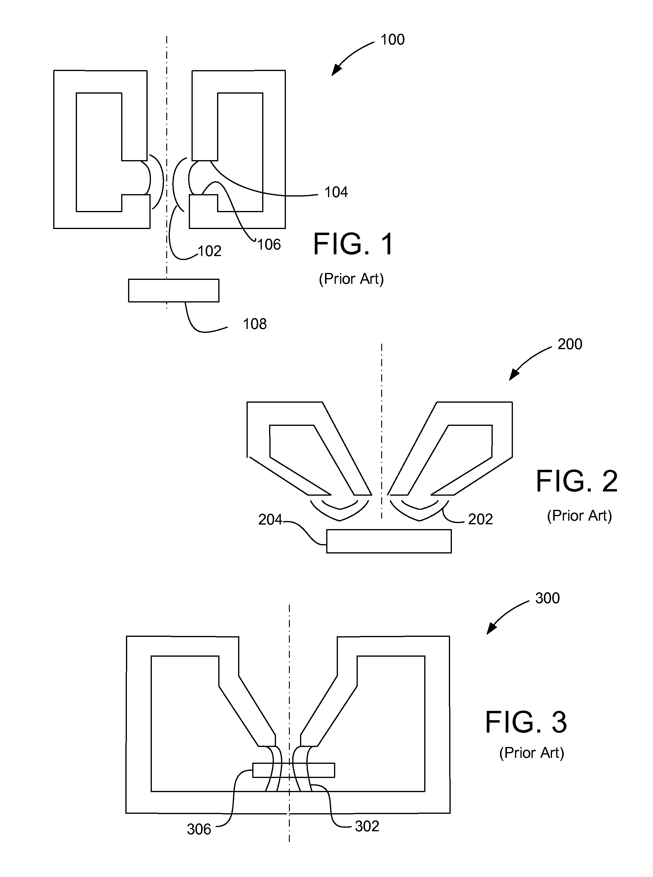
Unfortunately, the magnetic field produced by the electron lens deflects the ion beam from its intended path due to the Lorentz force on the ions.
One solution is to the deflection of the ion beam by the magnetic field is simply to not operate the electron lens in immersion mode when using the FIB, but non-immersion modes typically have lower resolution.
Turning the SEM lens on and off, however, creates additional problems.
This time dependent field changes the trajectory of the ions, making it difficult to use the FIB.
A snorkel lens, however, produces a weaker magnetic field at the sample than does an immersion lens and has lower resolution.
Most ion beam systems do not include magnetic deflections lenses, and so the solution of Takeuchi requires extensively redesigning the FIB column to incorporate the magnetic lenses, and the redesign presents additional problems.
Although dual beam systems with a magnetic immersion mode SEM have been available for many years, they have been unable to operate the FIB when the SEM is operating in immersion mode.

Method used


Image

  • Dual beam system
  • Dual beam system
  • Dual beam system

Examples


Embodiment Construction

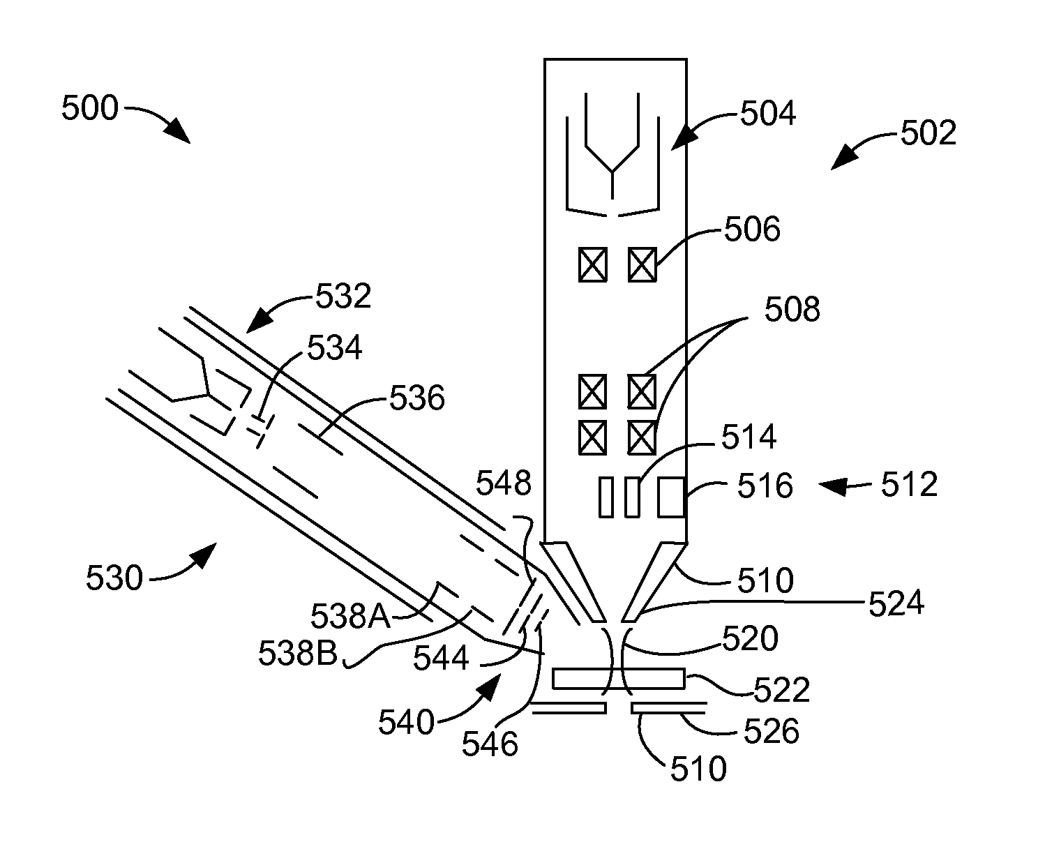
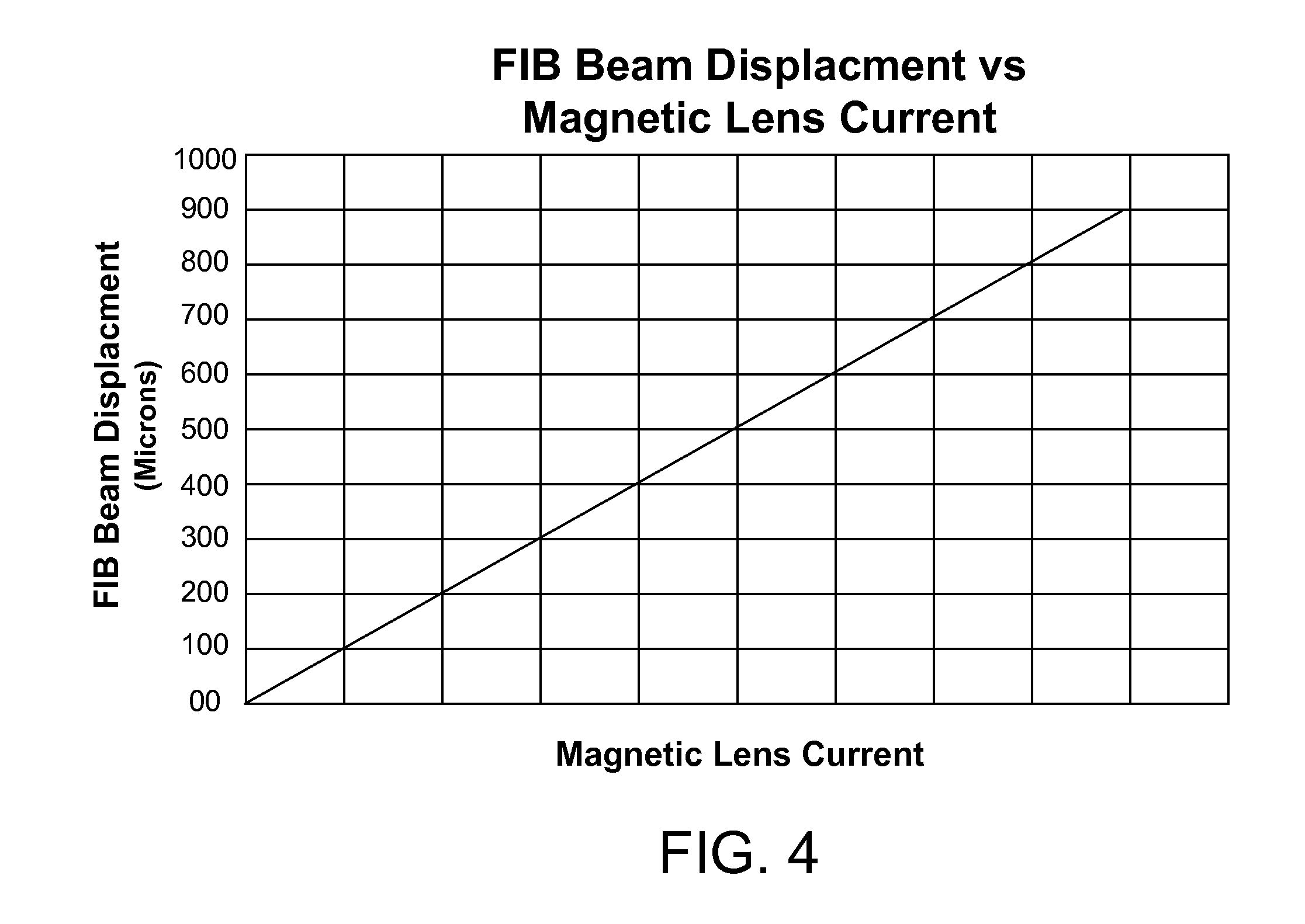
[0028]While an ion beam might be intentionally deflected to compensate for the deflection by the magnetic field of the SEM lens, deflecting a beam typically increases the aberration of the beam, that is, it disperses the beam to distort or expand the spot size of the focused beam. While ideally all ions in an ion beam have exactly the same energy, the nature of real ion sources is such that there is always a small spread of energy among the ions in the beam. Ions having different energies will be deflected differently by the magnetic field. The difference in deflection due to different energies is referred to as chromatic aberration, and causes the beam to spread out and impact different points on the target. Ions having different energies will also be deflected differently by an electrostatic field. Because the magnetic force depends on the velocity and the electrostatic force does not, the dispersion of the deflected beam in a magnetic field caused by the ion energy spread is diff...


PUM


Abstract

A dual beam system provides for operation of a focused ion beam in the presence of a magnetic field from an ultra-high resolution electron lens. The ion beam is deflected to compensate for the presence of the magnetic field.

Description

[0001]This application claims priority from U.S. Provisional Pat. App. No. 61 / 181,989, filed May 28, 2009, which is hereby incorporated by reference.TECHNICAL FIELD OF THE INVENTION[0002]The present invention relates to charged particle beam systems that include multiple charged particle beam columns.BACKGROUND OF THE INVENTION[0003]Charged particle beam systems are used in a variety of applications, including the manufacturing, repair, and inspection of miniature devices, such as integrated circuits, magnetic recording heads, and photolithography masks. Dual beam systems often include a scanning electron microscope (SEM) that can provide a high-resolution image with minimal damage to the target, and a focused ion beam column (FIB) that can be used for imaging or to alter substrates by milling or deposition. In most cases, the SEM and FIB are mechanically coincident, that is, the impact points of both beams are nearly identical.[0004]One common application for a dual beam system is ...

Claims


Application Information

Patent Timeline
IPC IPC(8): H01J37/14H01J37/28H01J37/305H01J37/12
CPCH01J37/09H01J37/1471H01J2237/30472H01J37/3056H01J37/302
Inventor MILLER, TOM
Owner FEI CO
Learn More